Week 8 - Challenge 3 - Coin Holder Design
Aim -
Create the Coin Holder Plastic component through the given Class-A surface. To begin with, the tooling axis for the given Class-A Surface should be created meeting the requirements of the draft angle and at the end perform the Draft analysis on the model.
objectives :
- To ensure proper tree structure is followed
- To keep the design as per requirement
- All the sketches should be iso constrained
- To publish the Class A,B and C Surface.
TOOLING AXIS :
The tooling axis is defined as the direction in which the mold or core and cavity opens is the tooling axis.
- First create the point for the reference of tooling axis
- Now using point as a reference we create a line normal to the surface.
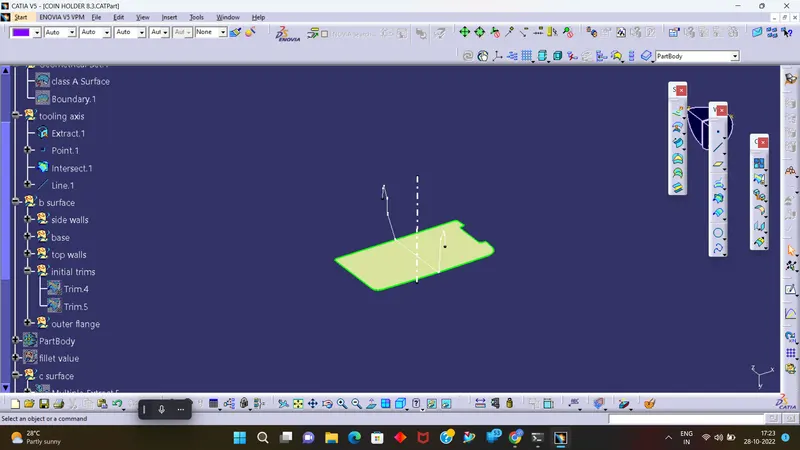
DRAFT ANALYSIS :
The Draft Analysis command enables you to detect if the part you drafted will be easily removed.
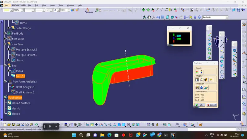
PERFORMING DRAFT ANALYSIS ON CLASS A SURFACE : -
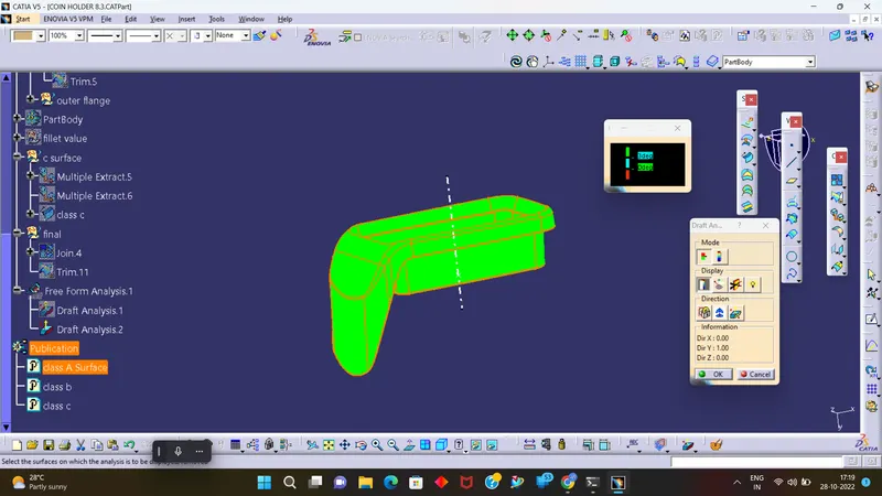
CLASS B SURFACE
Thickness of the component as 2.5mm. and create a B surface by using class A surface of an offset of 2.5mm
First we create a side wall and extract the class A surface and then create the base and upper tilt walls and other side supports
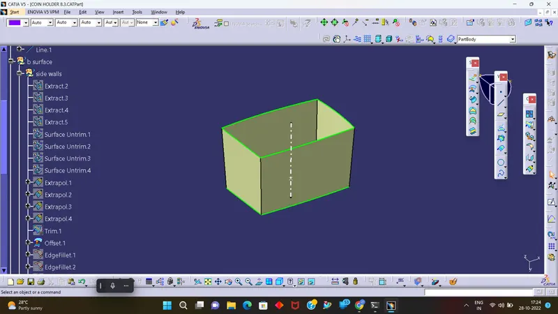
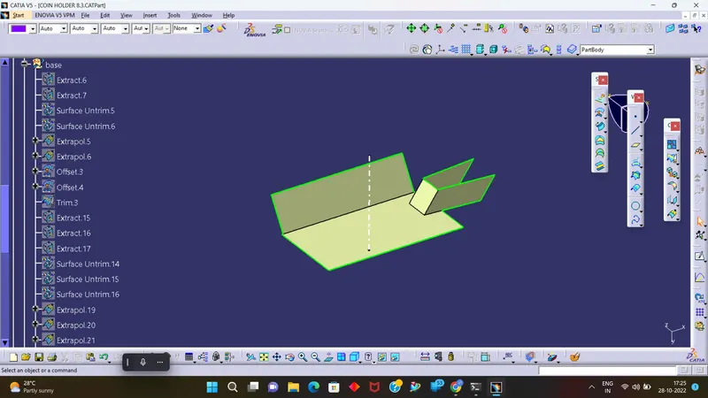
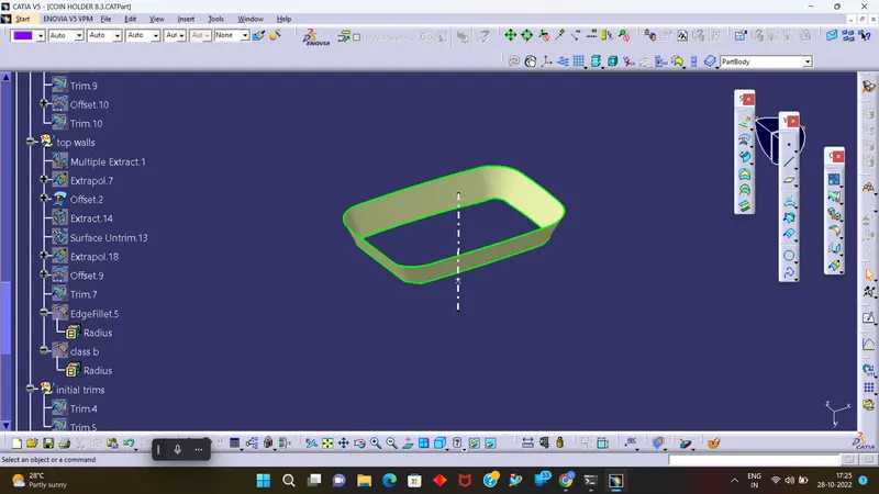
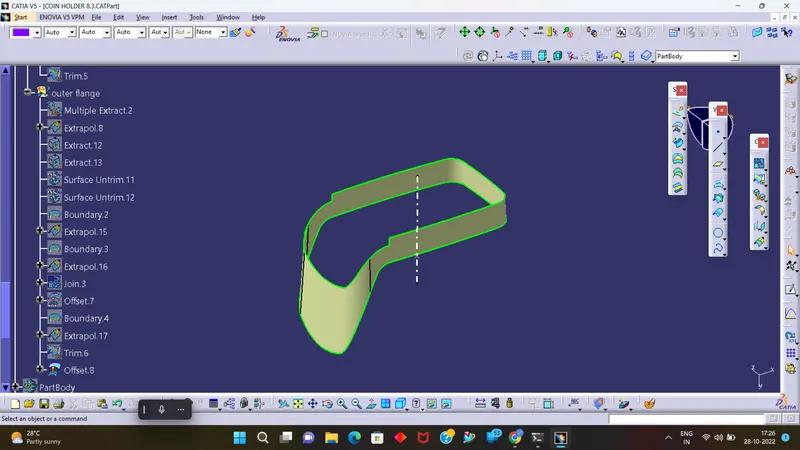
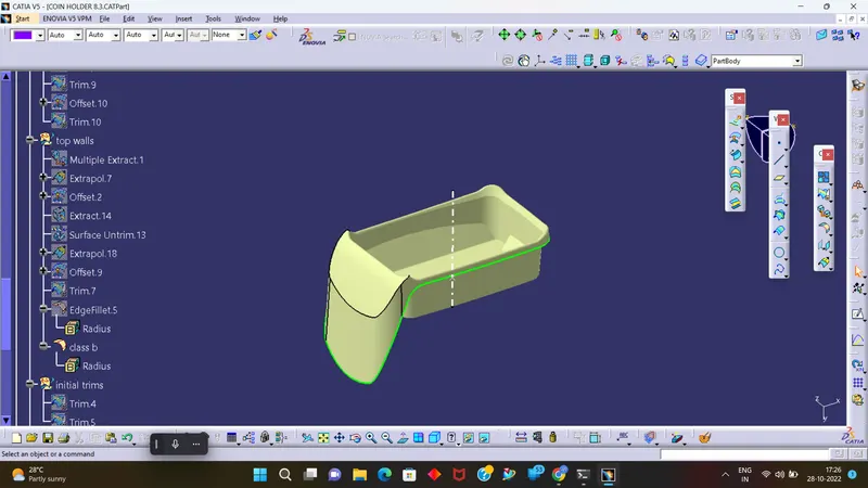
CLASS C SURFACE
NOW USING THE CLASS A SURFACE BOUNDARY, CREATED THE SIDE OF THE WALL AT (90+3) DEGREE OF 5MM. 3 DEGREE IS A DRAFT ANGLE.
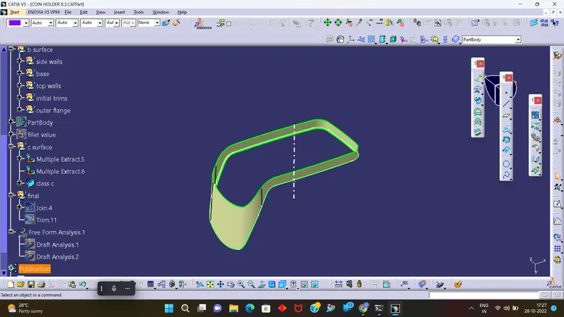
TRIM SURFACE :-
- After creation of class A, class B and class C surfaces, now we trim class b and class c surface to forma a new thick surface part, and then join the trimmed surface with class a surface to form the final required surface.
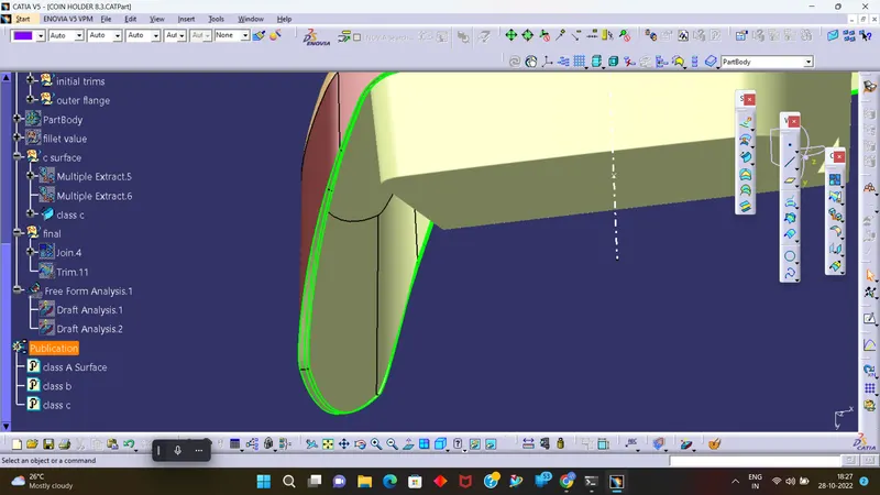
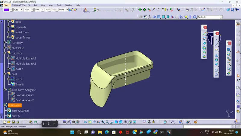
By using join join the class A,B and C surfaces together
Now by using closed surface command create a solid body
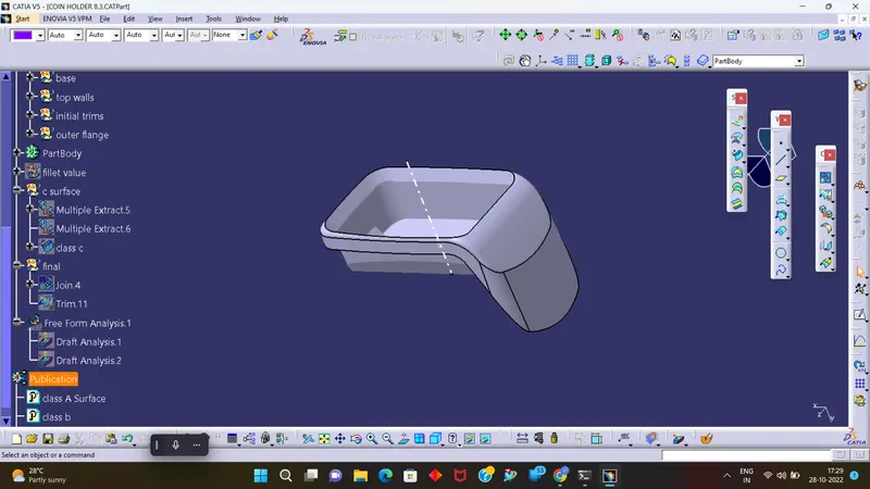
Draft Analysis for solid body
Red region shows due to negative draft value.
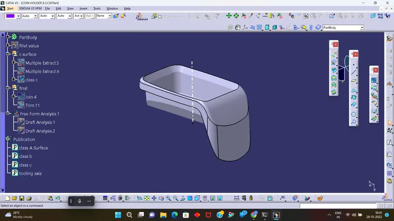
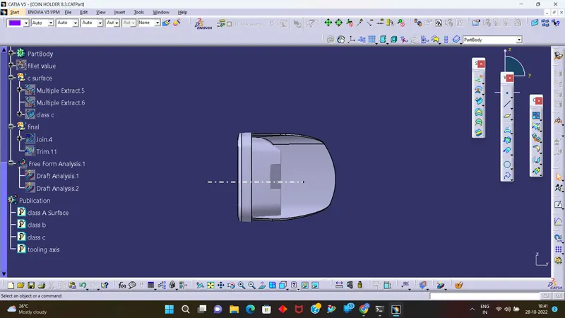
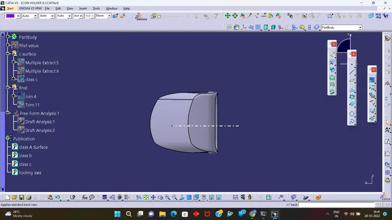
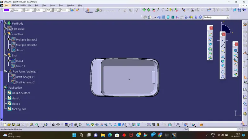
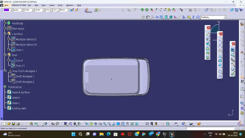
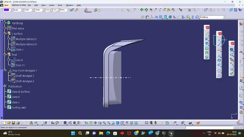
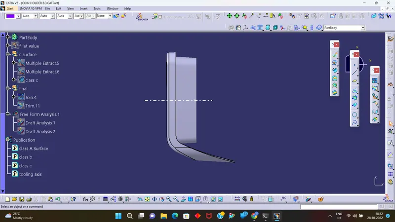
Screenshots of the solid model with the in various orientations Isometric, Front, Side, and Top View.
CONCLUSION :-
Coin holder plastic component using class A surface have been succesfully created and draft analysis performed.