Week 8 - Challenge 3 - Coin Holder Design
Aim
Create the Coin Holder Plastic component through the given Class-A surface. To begin with, the tooling axis for the given Class-A Surface should be created meeting the requirements of the draft angle and at the end perform the Draft analysis on the model.
Take the Thickness of the component to be 2.5 mm
INTRODUCTION:
CLASS-A SURFACE: A surface made by the designer which is given as an input to the plastic modeler/ sheet metal designer to work on. It is aesthetic surface and the outer most surface.
CLASS-B SURFACE: A surface below a certain thickness from the class-A surface is class-B surface. This is the surface that contains engineering aspects of a model for example Ribs cutout.
CLASS-C SURFACE: A surface that joins class-A and class-B surfaces together is called as a class-C surface.
Report
A detailed report should be done explaining the draft analysis and the tooling axis creation.
An explanation should be given on the way of creating the tooling axis, particularly the Bisecting method.
Tooling axis creation
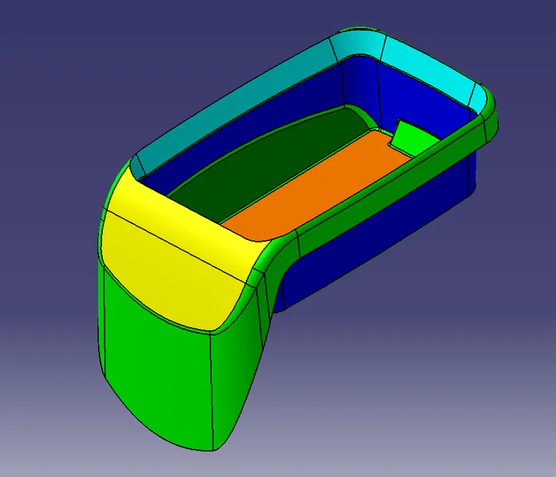
As in 3D we can see there are 4 side wall faces which are perpendicular to the base surface as in this situation we can draw a tooling axis normal to the surface
So first we extract the base surface and make a point at the centre and draw a line normal to that surface which is going to be the Tooling Axis
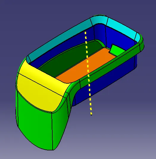
Bisecting Method
- The base surface of the class – A was extracted and a point at the centre is created and an axis system was inserted to the point with the current feature is disabled.
- Then, using project intersection along yz plane is created and the two inclined lines were drawn inside the positioned sketch.
- Then bisecting lines with the two inclined lines were drawn.
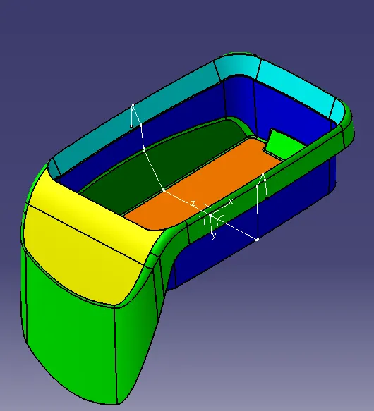
This is the Second method of creating a Tooling Axis so for that we draw a point at the base surface (Extracted earlier) and creat an Axis system at that point and then create the intersection between the Class A surface.
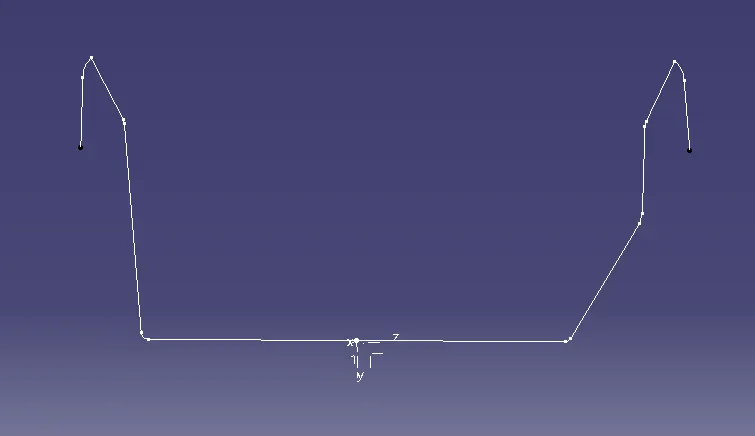
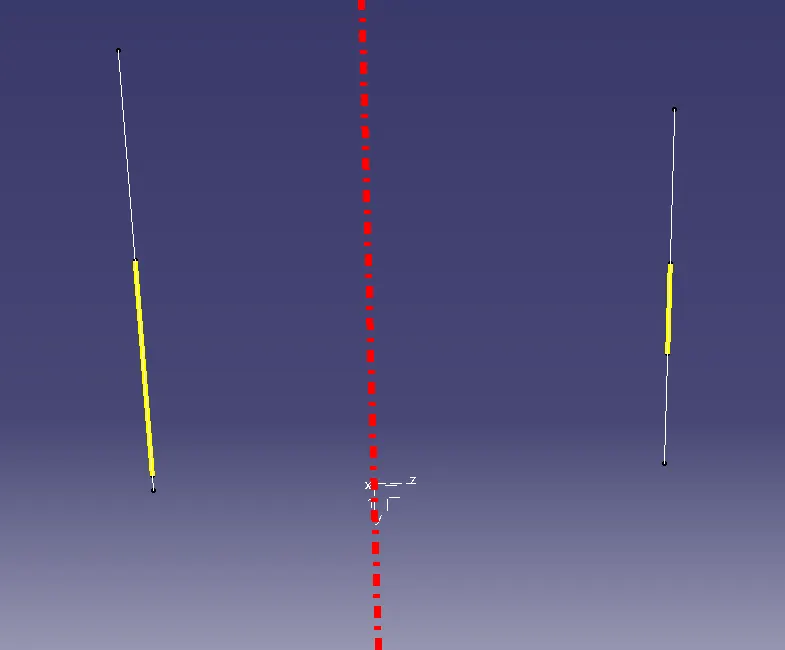
Then we extract the side lines and create 2 lines and then we use the bisecting line to create a line whicch is bisecting both the lines and this is going to be the Tooling Axis for the Class A Surface.
Procedure for creating B Class surafce
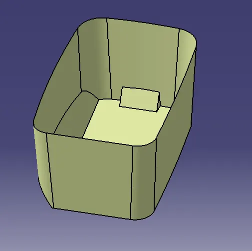
Side Walls:
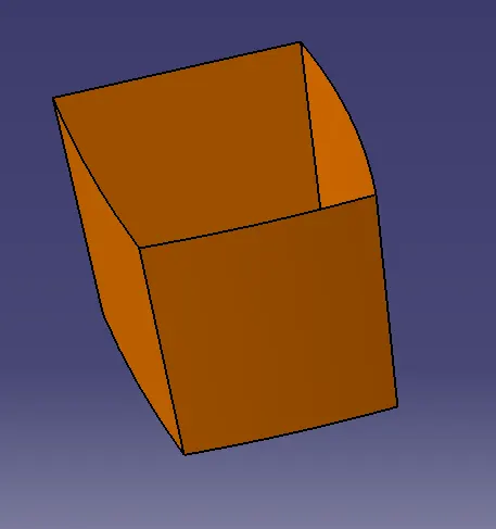
- Extract the side walls with no propagation in extract option.
- Untrim them.
- Extrapolate the walls with point continuity.
- Trim the walls to get the required shape.
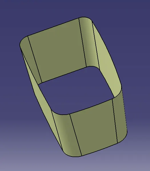
- Offset those trimmed walls with 2.5 mm thickness value.
- And then give the required fillet values by measuring the fillet of class A Surface
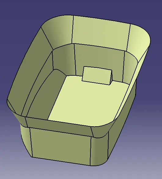
Top & Bottom Surfaces:
- Extract the surfaces separately and untrim them.
- Extrapolate the surfaces with required distances.
- Offset them with thickness value.
- Trim them for required shape.
Procedure for creating Class C Surface
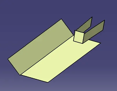
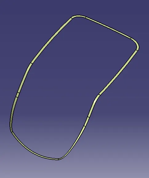
- Get the boundary lines of Class A surface separately.
- Extract the side wall surface and use the sweep command (With reference surface and give a 90 degree and 5 mm length inside)
Creating the final closed surface
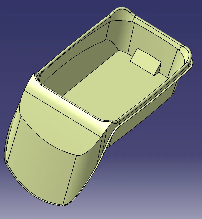
- Trim the Class C Surface with the Class B Surface
- Trim the class A surface with the trimmed surface (Class B + class C)
- And we will get the closed surface for the coin holder
- Go to part Body and use the closed surface to create a Plastic component
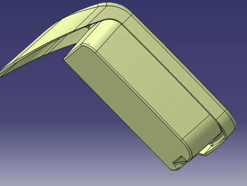
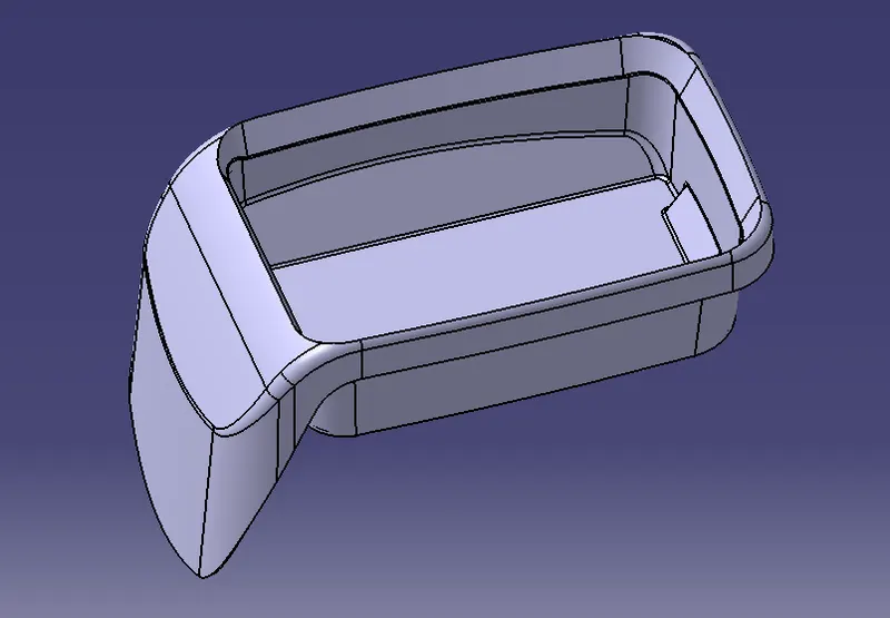
Draft Analysis for Solid Plastic Part
First the class – A surface is checked before creating the Class –B&C surface and finally the solid body must be analysed. Both can be done by following the below procedures.
By changing the view mode to custom view parameters – Material mode then the feature draft analysis is enabled.
Then the compass was activated and placed with the tooling axis by dragging the red pointer and then locked it.
Then, by selecting the quick analysis mode, the nominal value will be 3 degrees and checked for the component's draft angle.
The green colour area shows that it satisfies the 3-degree draft angle. If not satisfied then by using the Running point tool the area is measured and then altered to get a successful draft for the created tooling direction.
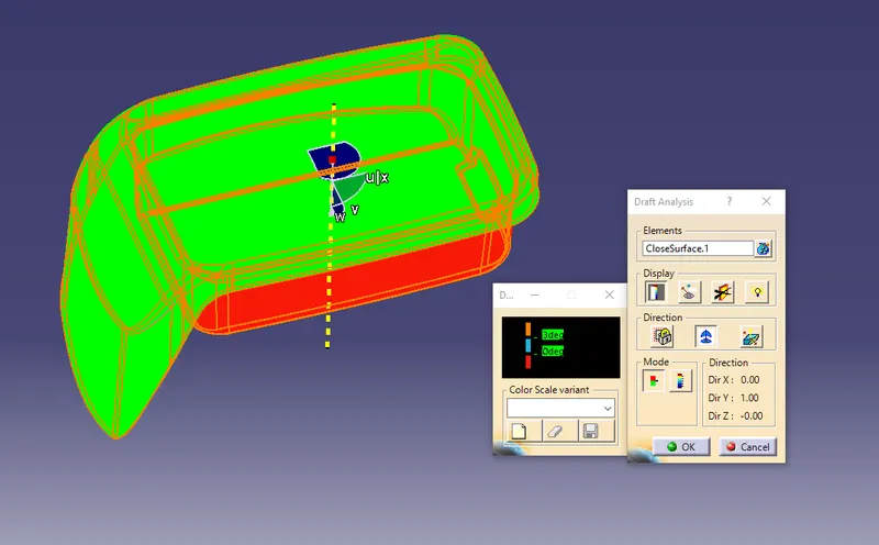
Draft Analysis of Class A Surface
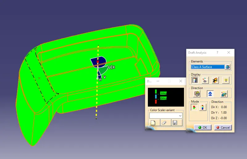
Colour Scheme
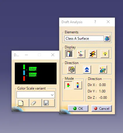
Screenshots of the solid model with the proper color code of the draft angle in various orientations (Isometric, Front, Side, and Top View)
Isometric View
Front Side
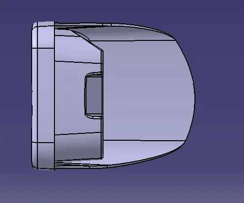
Side View
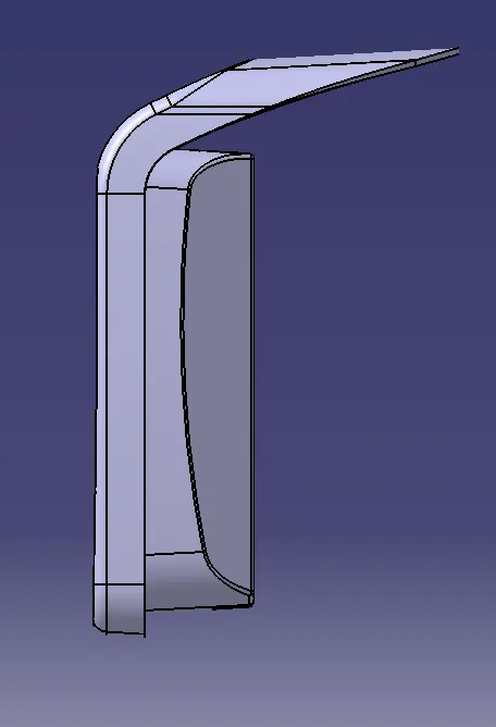
Top View
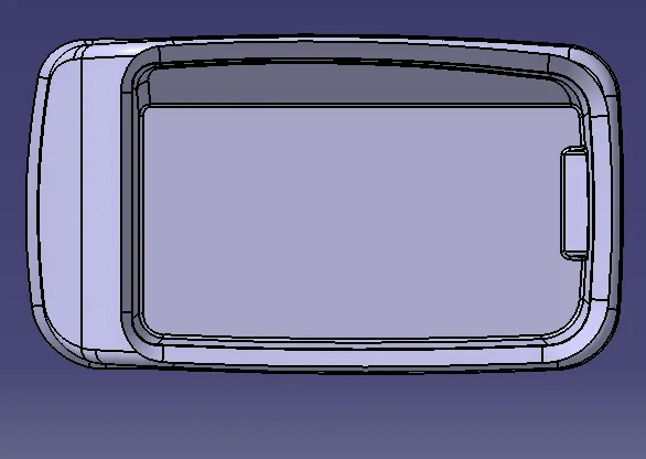
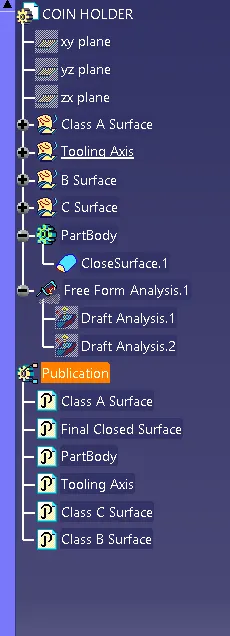
Tree Structure
Please find the attached part file for your review