Week 8 - Challenge 3 - Coin Holder Design
COIN HOLDER
Tooling Direction
The Tooling Direction is basically the direction that the molds pulls apart. The mold is built in two separate pieces, basically. You have a Cavity side and you have the Core side. The Core pulls apart from the Cavity and that pulling direction is the Tooling Direction.
Procedure
1. First observe the class A surface visually and create an approximate tooling direction (Dummy tooling axis).
2. Create necessary surface lines with the help of intersection curves in perpendicular planes.
3. Bisecting the surface lines in both perpendicular planes will produce tooling directions in respective planes
4. Finaly bisecting the tooling directions in perpendicular planes give the Final tooling direction we required.
Screenshots
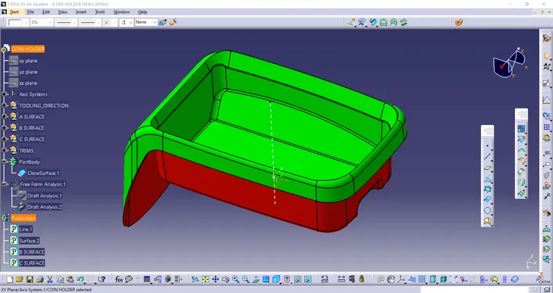
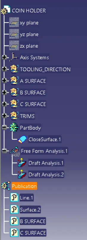
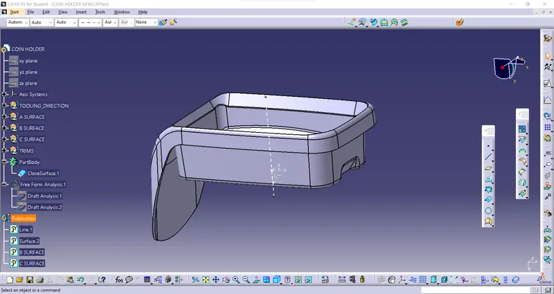
Specification Tree.
Draft Analysis.
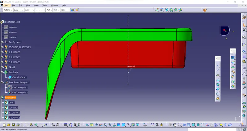
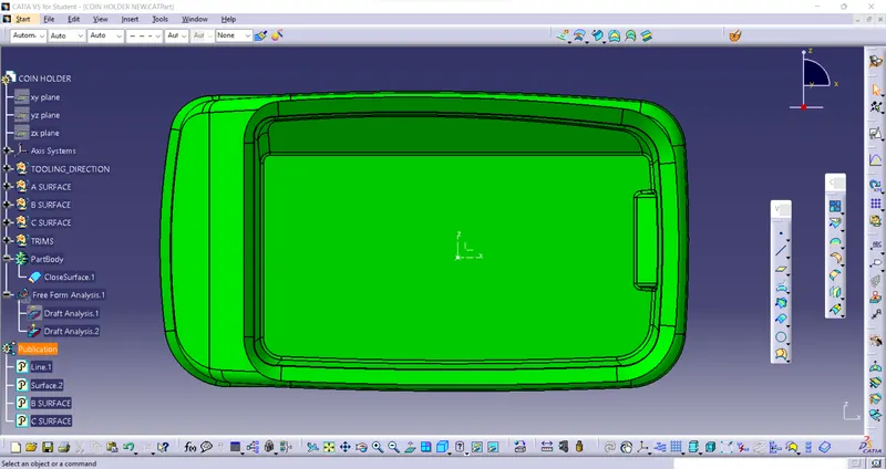
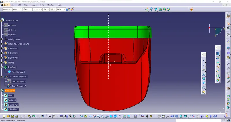
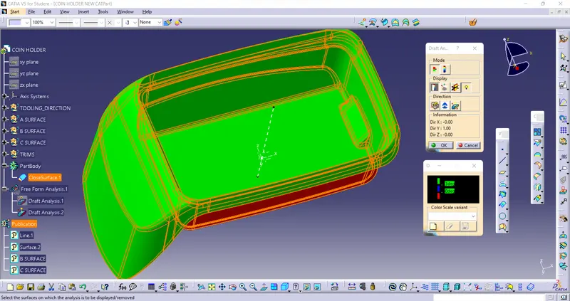
Drft Analysis will highlight the entire area of the model with different colour codes according to the rage of angle they have with the draft direnction. In this model we have set the green colour for angle more than 3 degree. Blue for the angle between 3 to 0 degree. And red for angle less than 0 degree.
For the ease of manufacturing we always preffer minimum of 1.5 degree. When it reduced further the complexity of manufacturing increases and thus the cost increases. If we require some undercuts then we need to use side cores.
Different orientations