SUNSEEKER PREDATOR YACHT- Modeling and Rendering in SOLIDWORKS
SUNSEEKER PREDATOR YACHT
Introduction
A yacht is a sail or power vessel used for pleasure, cruising or racing. Cruising yachts may be designed for near-shore use or for passage-making. They may also be raced, but they are designed and built with the comfort and amenities necessary for overnight voyages. Qualities considered in cruising yachts include: performance, comfort under way, ease of handling, stability, living comfort, durability, ease of maintenance, affordability of ownership. Depending on size, a cruising yacht is likely to have at least two cabins, a main salon and a forward stateroom. In smaller yachts, the salon is likely to have convertible berths for its crew or passengers. Typically, the salon includes a dining area, which may have a folding, built-in table. The development of reliable power plants created a new category of pleasure craft. The power plants for yachts started with the steam engine and transitioned to the internal combustion engine. Originally the material for all yachts were made of wood, using a wooden keel and ribs, clad with planks. These materials were replaced with iron or steel in steam yachts. In the 1960s fiberglass became a prevalent material. Larger yachts are more likely to be constructed of steel, aluminum or composite fiber-reinforced plastic.
Through this project with the aim to acquire skill in CAD, we are designing a Yacht in Solidworks. For the design we predominantly use surface modeling because the hull and superstructure include irregular and curvy geometries. Solid modeling comprises a minor portion for this design.
--------------------------------------------------------------------------------------------------------------------------------------------------------------------------------------------------------------------------
Objective
- To design and model the parts for a cosmetic version of Sunseeker Predator Yacht.
- Assemble the parts to produce the final model.
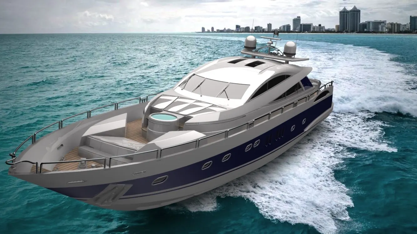
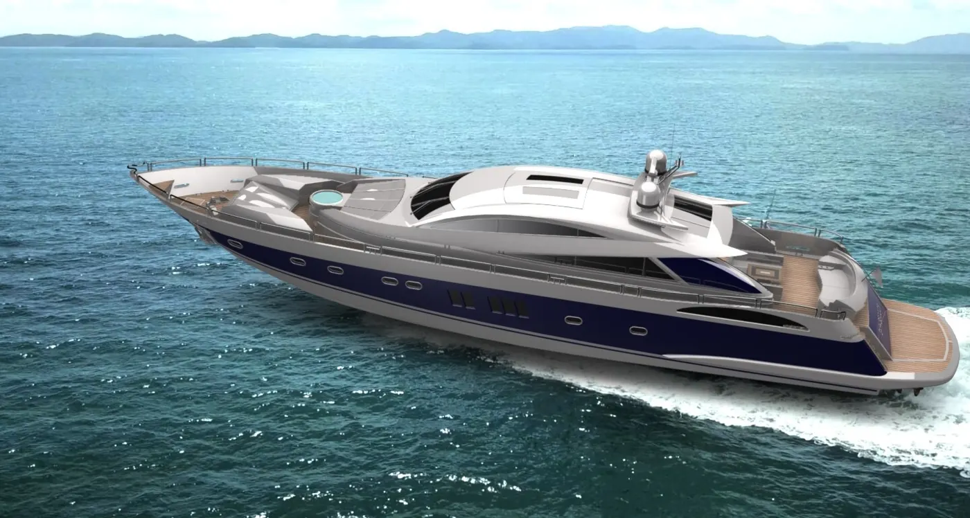
- Perform some photorealistic rendering for the model.
--------------------------------------------------------------------------------------------------------------------------------------------------------------------------------------------------------------------------
Explanation for Parts
- Propeller
A propeller is a device with a rotating hub and radiating blades. It transforms rotational power into linear thrust by acting upon a working fluid, such as water or air. In this case the working fluid is water.
(Features used: Sketch, Revolve, Loft, Fillet, Cut Extrude, Circular Pattern.)
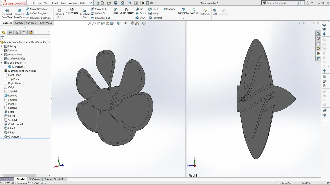
Fig 1: Propeller of the yacht.
- Radar
Radar is a detection system that uses radio waves to determine the range, angle, or velocity of objects. In yacht it is used to detect the obstacles in the path. A radar system consists of a transmitter producing electromagnetic waves in the radio or microwaves domain, a transmitting antenna, a receiving antenna (often the same antenna is used for transmitting and receiving) and a receiver and processor to determine properties of the objects. Radio waves from the transmitter reflect off the object and return to the receiver, giving information about the object's location and speed.
(Features used: Sketch, Boss extrude, Fillet, Cut Extrude, Sketch pattern, Mirror, Split Line)
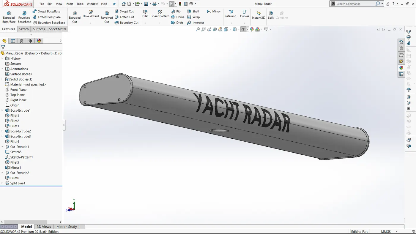
Fig 2: Radar
- Hull
A hull is the watertight body of a ship or boat. The hull may open at the top, or it may be fully or partially covered with a deck. Atop the deck may be a deckhouse and other superstructures, such as a funnel, derrick, or mast. The line where the hull meets the water surface is called the waterline.
(Features used: Sketch, 3D Sketch Offset Entities, Projected Curves, Trim Surface, Lofted Surface, Extruded Surface, Fill surface, Knit, Shell, Extruded Boss, Extruded Cut, Fillet, Chamfer, Swept Boss, Revolve, Dome, Helix/Spiral, Linear pattern,Delete Face, Mirror, Split Line, Split Body, Offset Surface.)
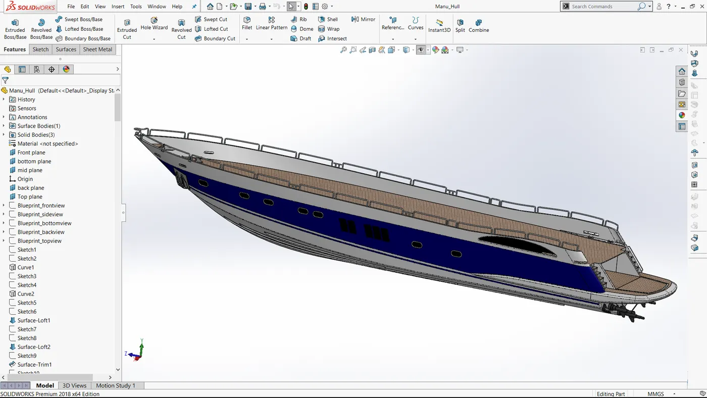
Fig 3: Hull
- Garage Door
Garage door cover the garage space. The garage space is cut from the hull in to a new body to create the door for the same.
(Features used: Split Body, Sketch, Extrude Cut, Shell, Fillet, Mirror)
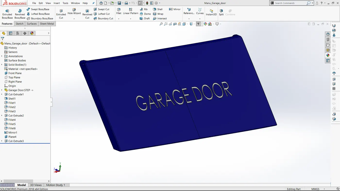
Fig 4: Garage Door
- Front Seat
Front seat is place above the deck surface along with the superstructure. In order to create the front seat we imported the deck surface as reference.
(Features used: Sketch, Reference Plane, Surface Sweep, Surface Trim, Surface Loft, Knit, Surface Fill, Chamfer, Revolve, Cut Extrude, Fillet, Dome, Mirror)
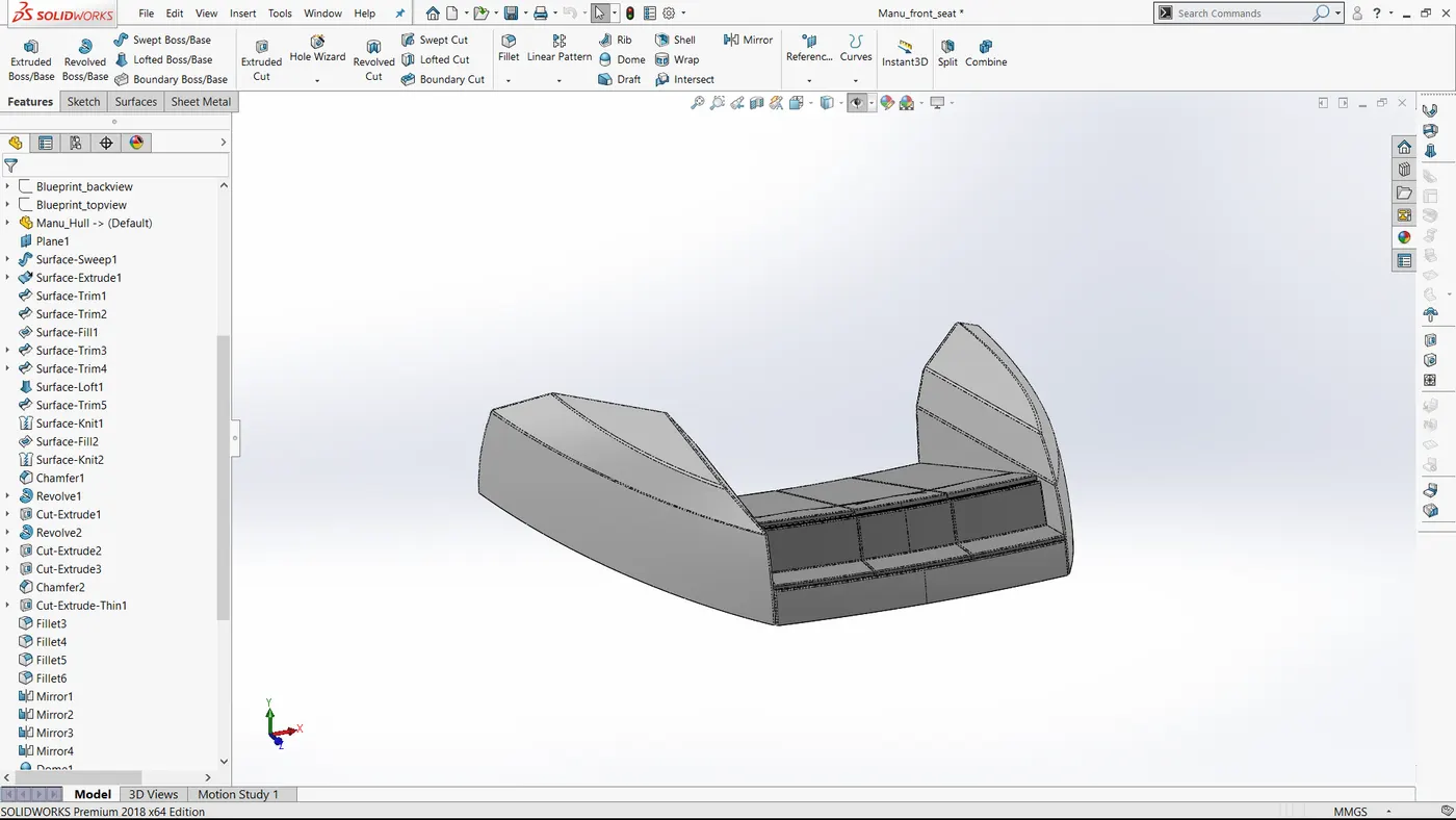
Fig 5: Front Seat
- Middle Seat
Middle seat is placed just behind the superstructure, on the deck surface. We imported the deck surface as a reference. The middle seat also include a Table at its center.
(Features used: Sketch, Boss Extrude, Chamfer, Fillet, Extruded Cut, Mirror)
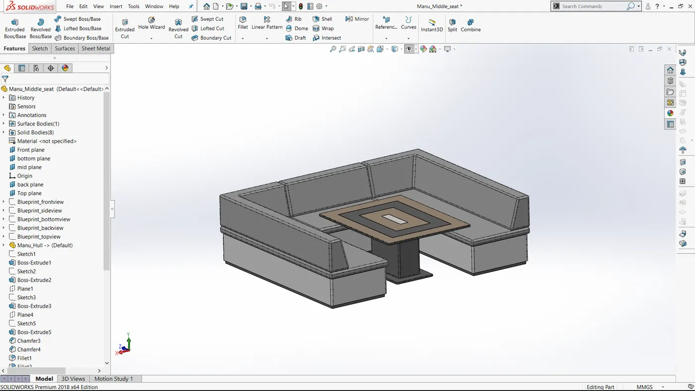
Fig 6: Middle Seat
- Rear Seat
Rear seat is place at the end of deck surface. We use deck surface as the reference for the rear seat.
(Features used: Sketch, Offset Entities, Offset Surface, Trim, Ruled Surface, Knit, Extend Surface, Extruded Surface, Lofted Surface, Extruded Cut, Chamfer, Fillet, Mirror, Revolve, 3D Sketch)
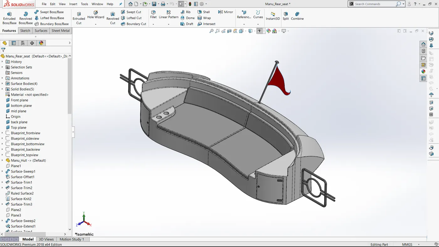
Fig 7: Rear Seat
- Superstructure
The structure or body above the deck surface is called superstructure. In order to reduce drag it is necessary to have an aerodynamic shape. It covers the cabin and living area of the yacht. Here also we use the deck surface as the reference.
(Features used: Sketch, 3D Sketch, Offset Entities, Convert Entities, Extrude Surface, Swept Surface, Knit Surface, Ruled Surface, Extend Surface, Trim Surface, Loft Surface, Fill Surface, Projected Curve, Delete Face, Thicken Surface, Extruded Cut, Dome, Split Line, Mirror)
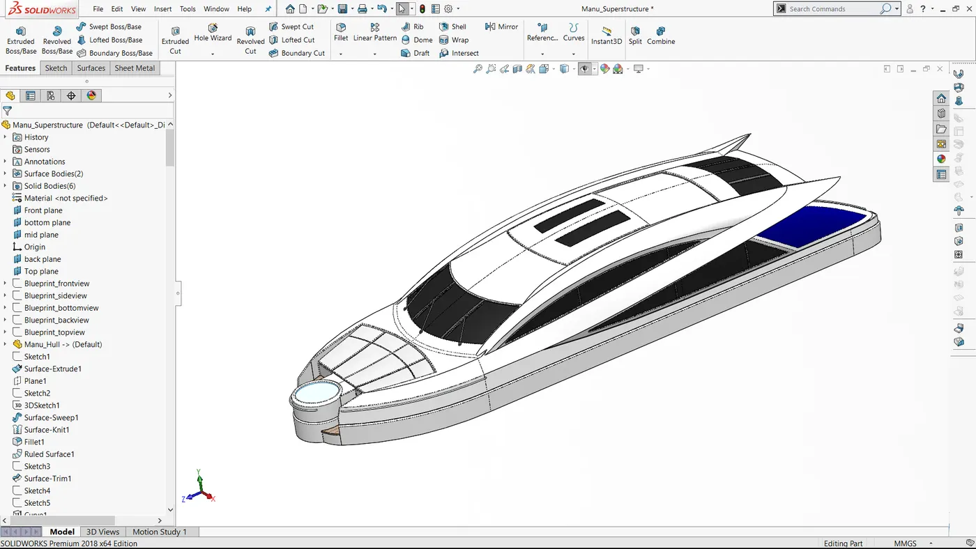
Fig 8: Superstructure
- Radar Mast
Radar mast Support the Radar antenna, Satellite receivers, Light, Horn. We use the top surface of the superstructure as the reference for the radar mast.
(Features used: Sketch, Offset, Extruded Boss, Revolve, Swept, Mirror, Shell, Chamfer, Projected Curve, Dome, Fillet)
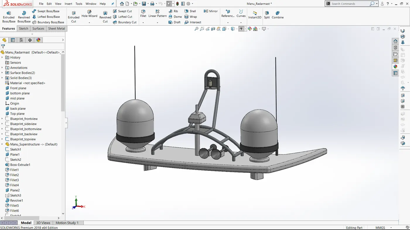
Fig 9: Radar Mast
--------------------------------------------------------------------------------------------------------------------------------------------------------------------------------------------------------------------------
Assembly
In Assembly first we imported the hull of the yacht. Then fixed other parts using mate conditions. The different mates we used are Concentric mate, Coincident mate, Distance mate.
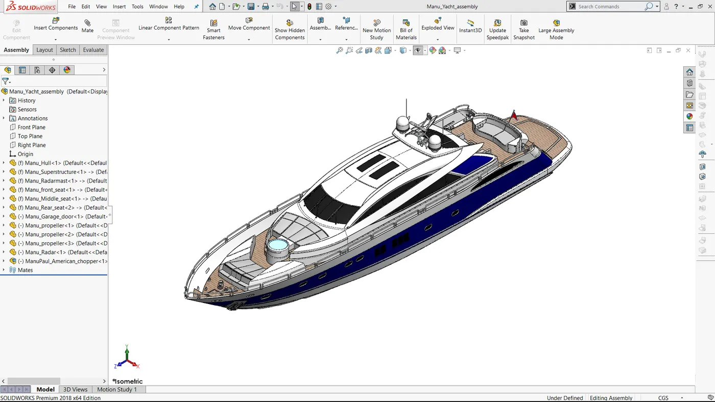
Fig 10: Assembly of Yacht
--------------------------------------------------------------------------------------------------------------------------------------------------------------------------------------------------------------------------
Rendering
Photoview 360 (Solidworks add-ins)
Applied Appearance, Scene, Environment, cameras, Lights
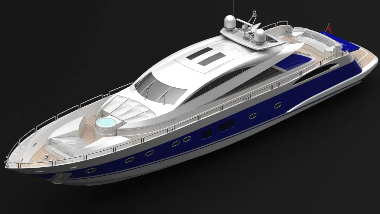
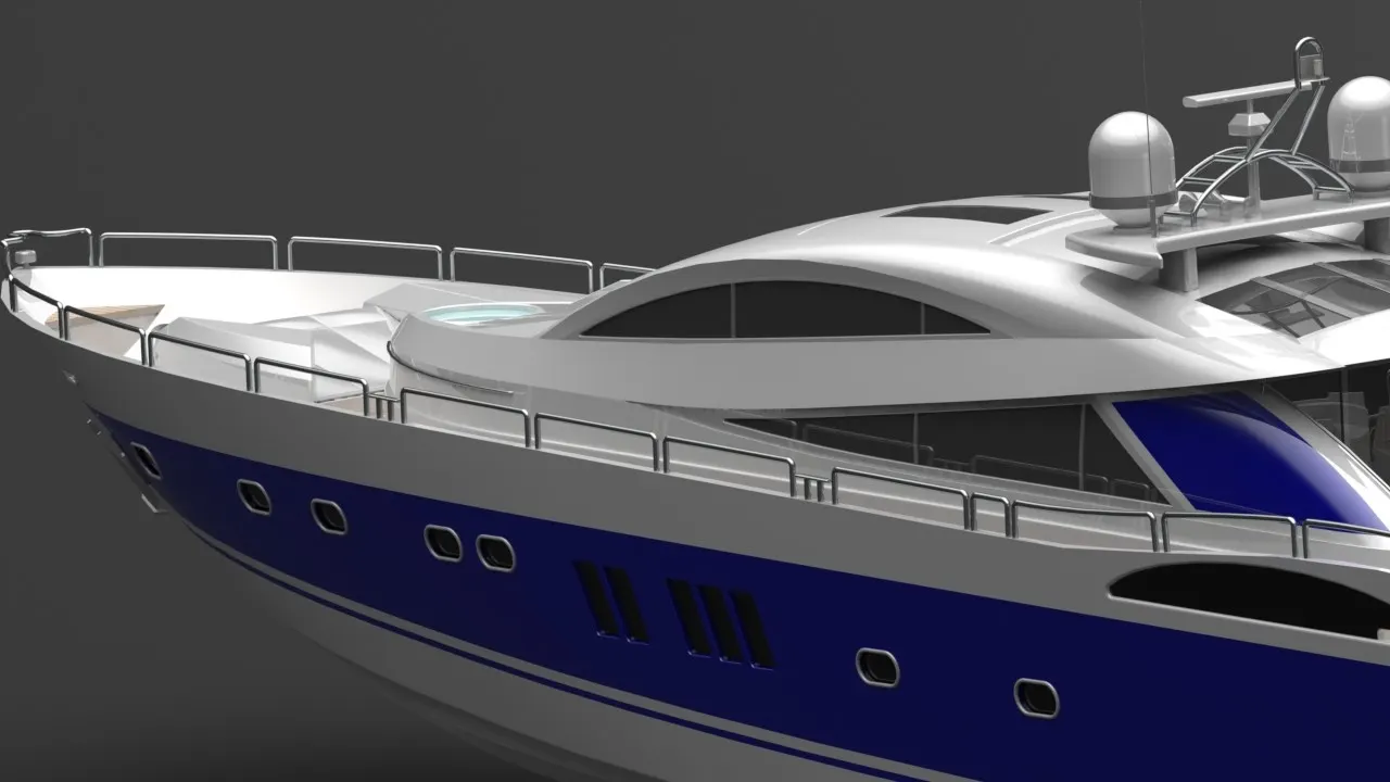
Solidworks Visualize
Applied Environment, Back Plates, Cameras.
--------------------------------------------------------------------------------------------------------------------------------------------------------------------------------------------------------------------------
Result And Conclusion
Designed and modeled the parts for the yacht, assembled them to produce the final model. Also done some photorealistic rendering.