Week 8 - Challenge 2 - Switch Bezel Design
Aim: Create the Switch Bezel Plastic component through the given Class-A surface.
-Objectives:
- To create class B & C surface for the given component.
- To form the tooling axis and capture the surface properly.
- To check the feasibility of the component with a draft of 3 degrees.
Method:
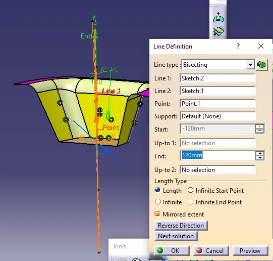
- In order to obtain the proper draft analysis tooling axis is required and the following steps show how it is done.
- As this component has 1 hole from where the tooling axis can be generated, however it does not have proper 4 walls to generate it. In this case, an approximation is made in order to obtain the tooling axis.
- First by using the two side walls a dummy axis is made. As it is known that the draft angle is 3 degrees, the second axis is taken as a 3 degrees to the given wall and using these two axis the tooling axis is made.
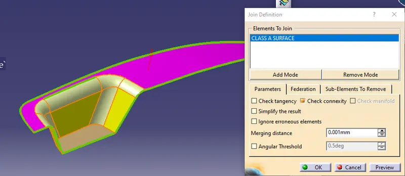
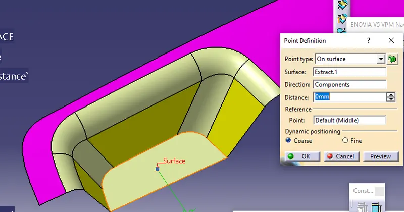
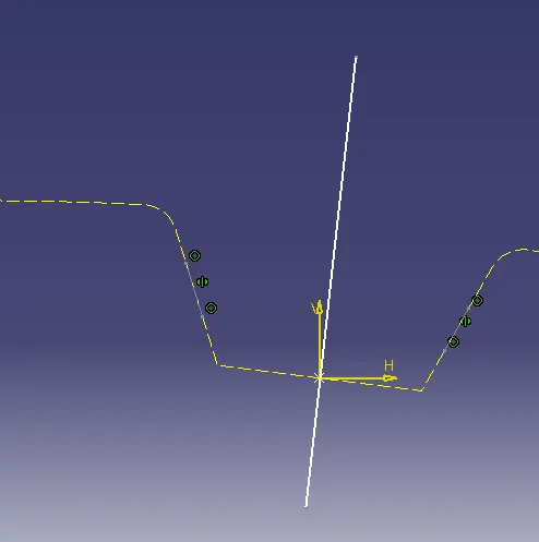
Using the two side walls 1st axis is made.
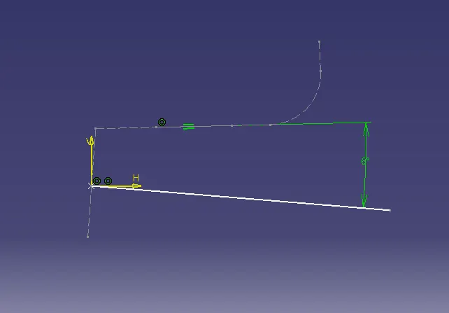
As the 4th wall is not there, an assumption is made and the axis is taken which is 3 degrees from the horizontal axis.
Creating_Class_B_Surface:
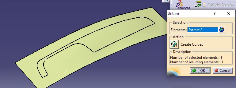
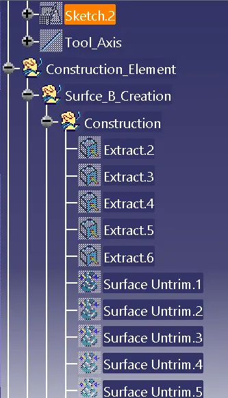
To start with, the top rest surface is extracted and untrimmed and extrapolated, so that this can be used to trim with other surface to form the class B surface.
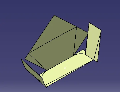
Likewise, other surfaces are also taken, untrimmed and extracted to trim with the adjoint surfaces.
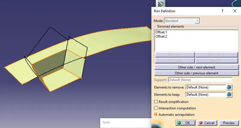
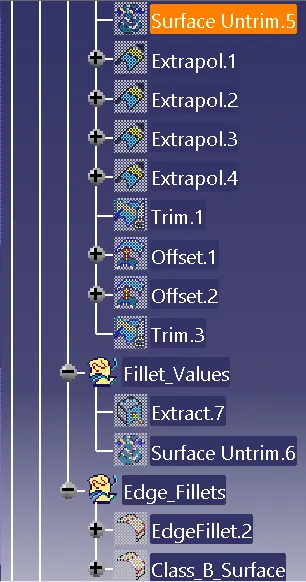
Once all the untrimed then extrapolate all the surface and offset to distance of 3mm and trimed it.
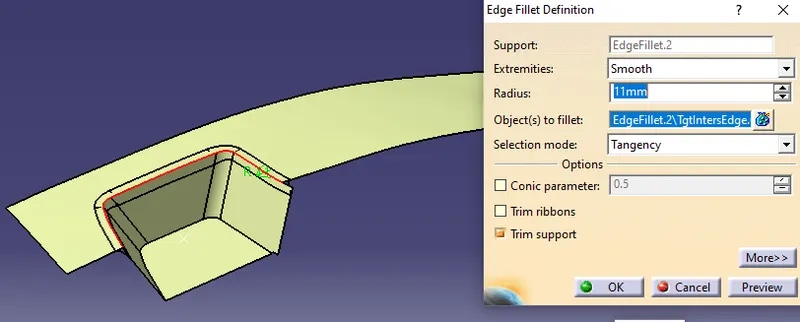
As per the requirement, the fillets are given. In order to given the fillets it is not exactly equal to class A. Along with the fillet radius, part thickness has to be added.
Creating_Class_C_Surface:
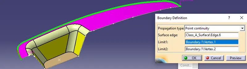
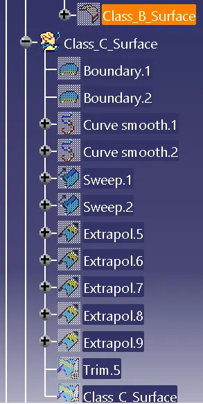
Created two separate boundary as shown in above images.
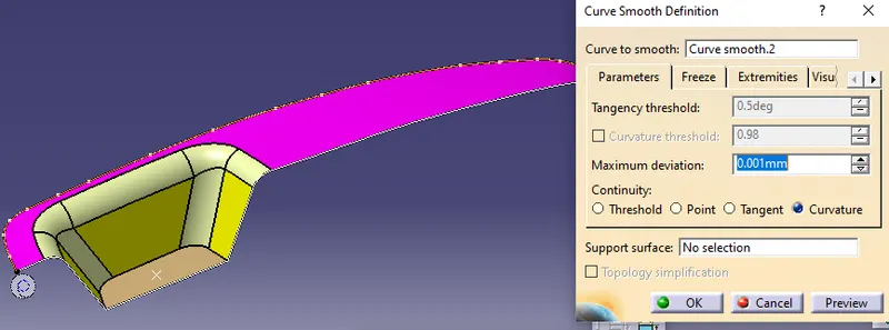
Given smooth curve to the two boundarys
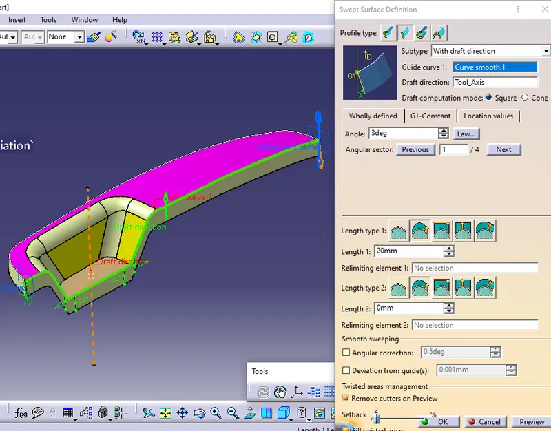
Created surface by using sweep command with reference to draft direction here the direction we are considered an tool axis and draft angle given minimum 3 degree as per draft angle condiions.
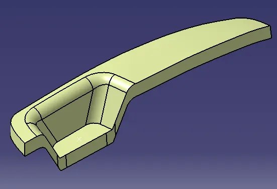
Modified the sufaces by using extrapolate and trim command then finaly created class_c_surface as shown in above image.
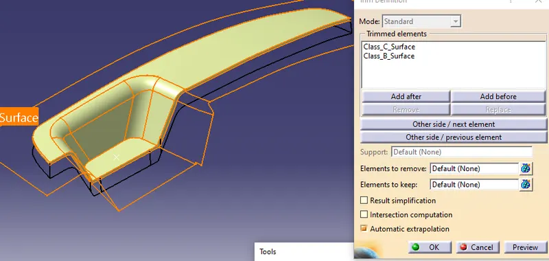
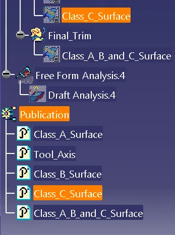
Given final trim to class_c_Surface and class_c_surface.
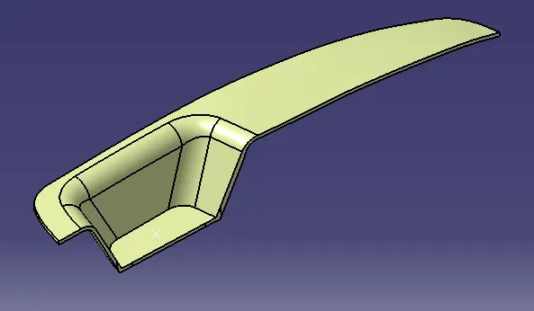
Closed surface.
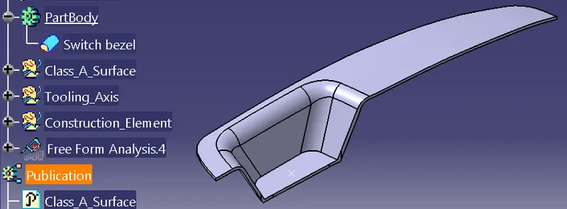
Thickness given to the closed surface by using close surface command.
Draft analysis:
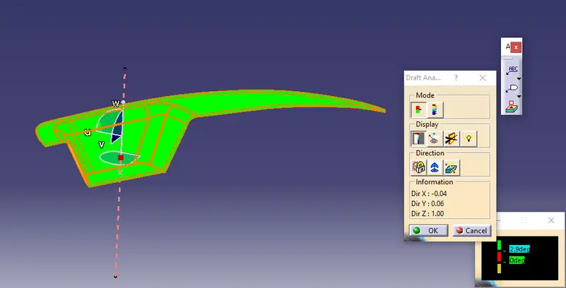
As shown in above image modified the tooling direction and finaly done the draft analysis for the part and angle dimensions are shown in above image.
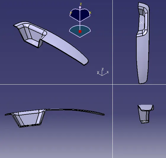
3D Model Views Isometric view, Front view, Top view, Side view.
Publications:
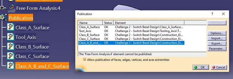
Publications are done as per the given gudeliness.
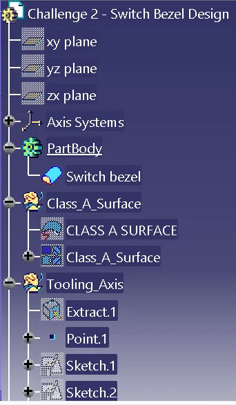
Tree Structure:
Learning outcome:
- How to form the tooling axis when there are constraints on the number of walls.
- To capture the class B and C properly.
- To check the feasibility of the component.