Week 8 - Challenge 2 - Switch Bezel Design
Week 8 - Challenge 2 - Switch Bezel Design
AIM:- Create the Switch Bezel Plastic component through the given Class-A surface. To begin with, the tooling axis for the given Class-A Surface should be created meeting the requirements of the draft angle and at the end perform the Draft analysis on the mode
OBJECTIVE:-
- Creation of Tooling Axis.
- Creation of class B and C surface.
- Creating a soild part out of surface modelling.
- Draft Analysis of class A Surface and final plastic component.
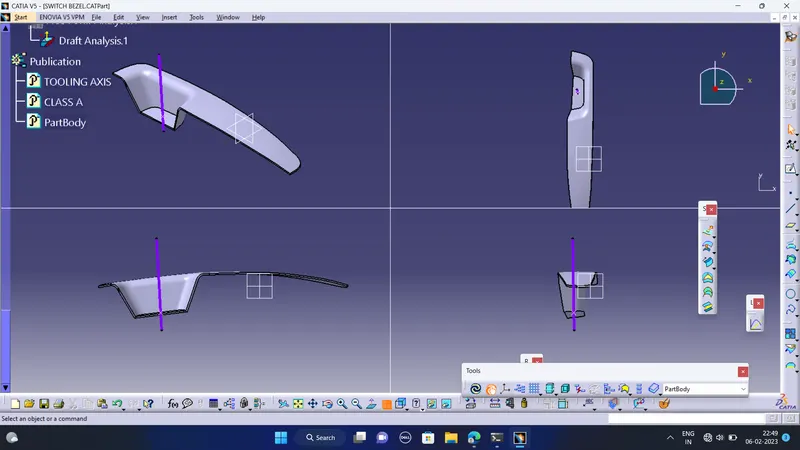
CLASS A:- Following Surface is given as the input for the component creation.
Creating of Tooling Axis:
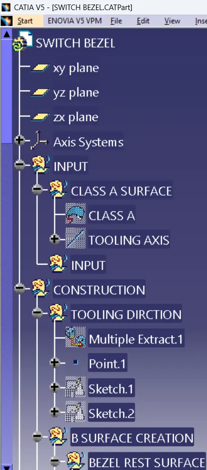
- Hence the tooling direction is created by considering the above factor and bisecting method is used.
- The base surface of the class – A was extracted and a point at the centre is created and an axis system was inserted to the point with the current feature is disabled.
- Then, using project intersection along yz plane is created and the two inclined lines were drawn inside the positioned sketch.
- Then bisecting lines with the two inclined lines were drawn.
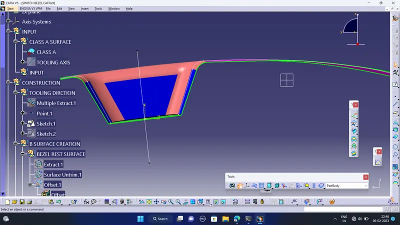
- Now the same procedure is done along the xz plane but on one side we don’t have inclined lines so the centre point is used to extrude a line along the z-direction and gave a measurement of 3 degrees (Tentatively).
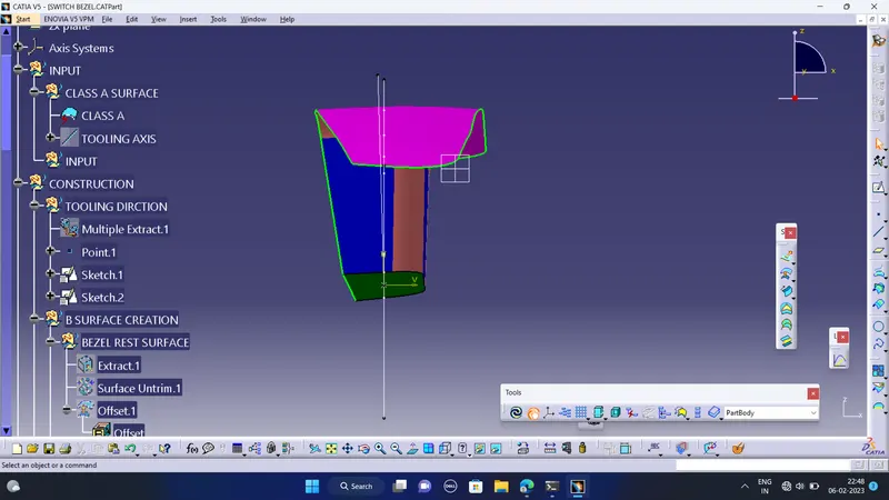
- With these two lines from sketches 1 and 2, the bisecting line is crated and published as Tooling Axis(tooling direction)
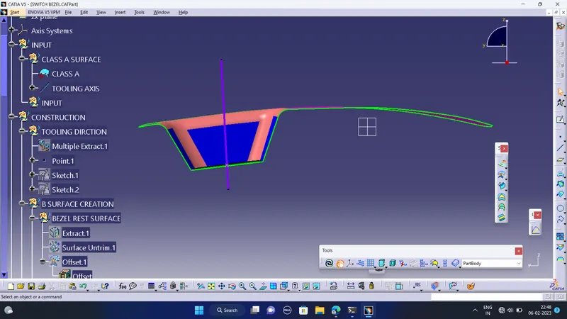
Creation of Class B Surface:
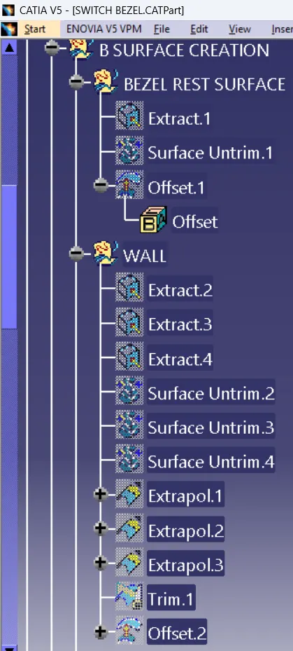
- For creating the class-B surface the required surface except the offset surface have been extracted and then untrimmed all the surface.
- Then all the surfaces have been extrapolated to get intersections between them.
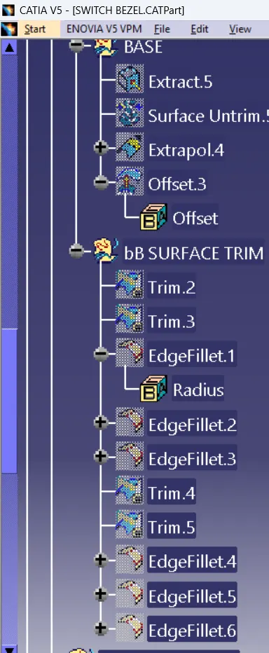
- Since the thickness of the Switch bezel is 2.5mm the B-Surface was offset to 2.5 mm and the required trim operations must be carried out.
- Finally, the required corners have been filleted to 12.5mm (15mm-2.5mm). [ 15mm - fillet value of the A-surface, 2.5mm – Thickness of the component ]
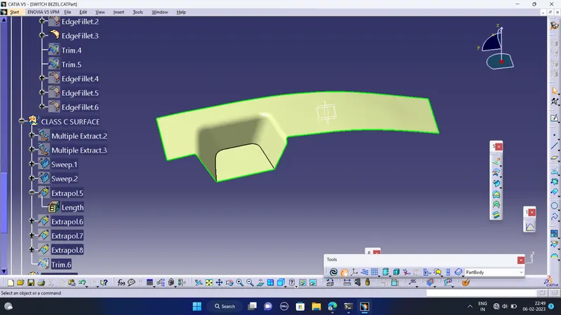
Creation of class c:
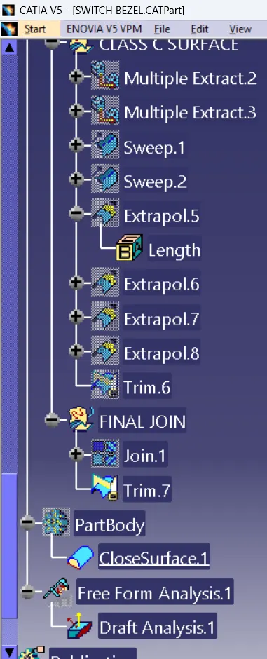
- For creating this surface we have to extracted the boundry of class A.
- Then by using the sweep command the surface was created with the following feature controls,
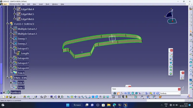
Final Trims:
Class A + Class C
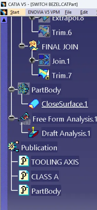
To make sure that there is not any open boundry between class A and Class c, we have used join option to created the single body. This is done to make sure that the parting line doesnt lie between the these two surfaces.
Class A + Class B + Class C
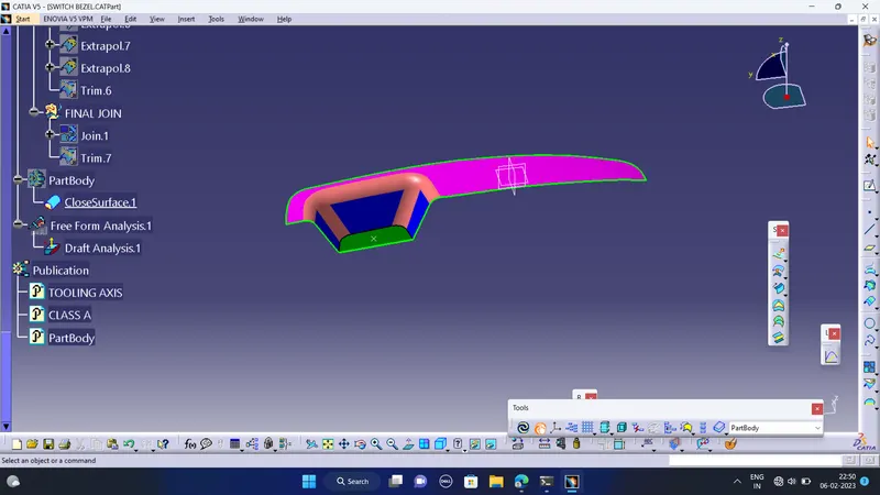
For this we have trimmed the join of the class A and class C Surfaces With the Class B.
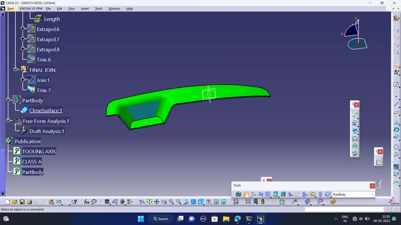
Then, by defining the part body by using the Closed Surface command in Part Design, the component's solid body is created.
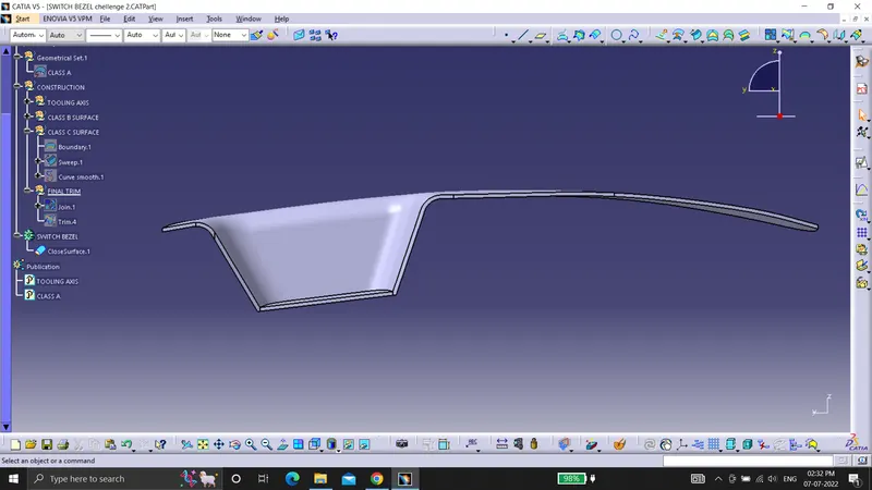
Specification Tree: