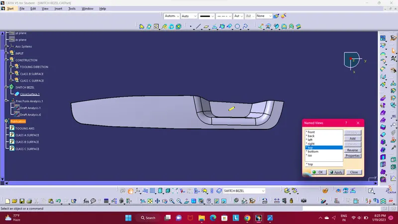
Week 8 - Challenge 2 - Switch Bezel Design
Challenge 2 - Switch Bezel Design
- Report
- A detailed report should be done explaining the draft analysis and the tooling axis creation.
- An explanation should be given on the way of creating the tooling axis, particularly the Bisecting method.
- Here i explain in steps how i complete the Tooling Axis creation.
- With the help of given Class-A Surface first i create a extract surface using [Extract Command].
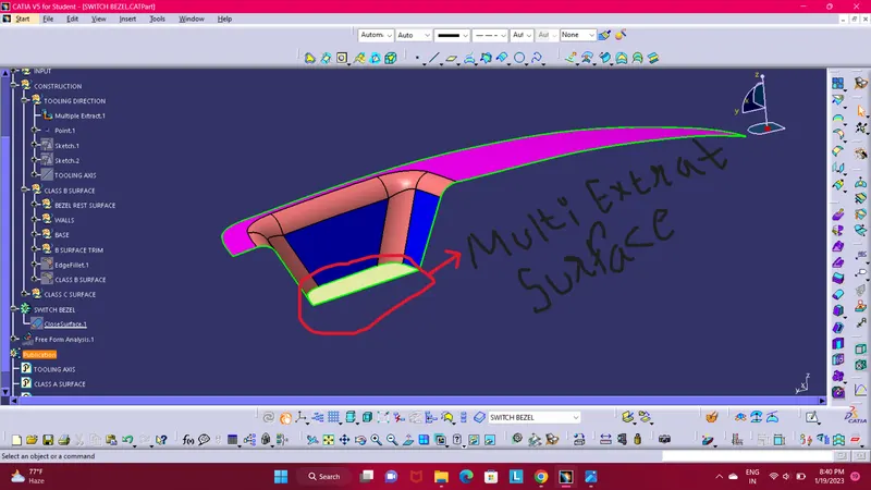
Etract Surface
- On a extracted surface create a point at centre. Using [Point Command] select point on surafce opt at zero distace.
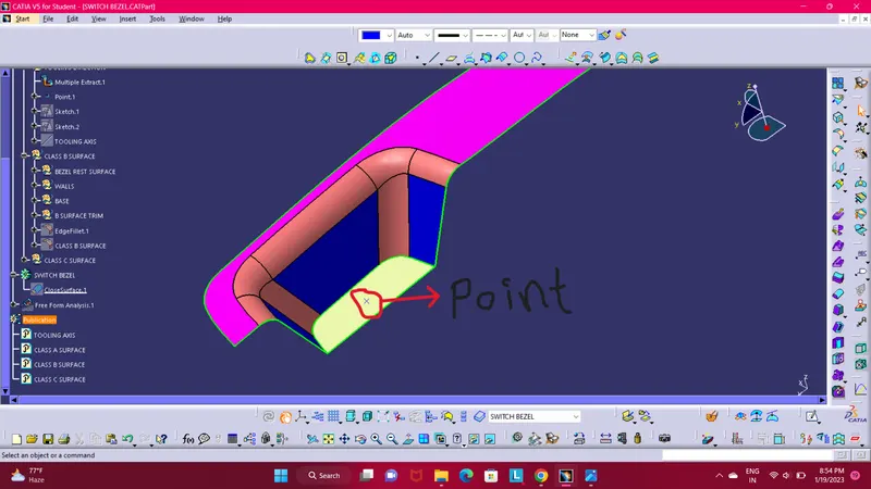
Point on EXtract Surface
- Create a axis on that piont using a [Axis System Command].
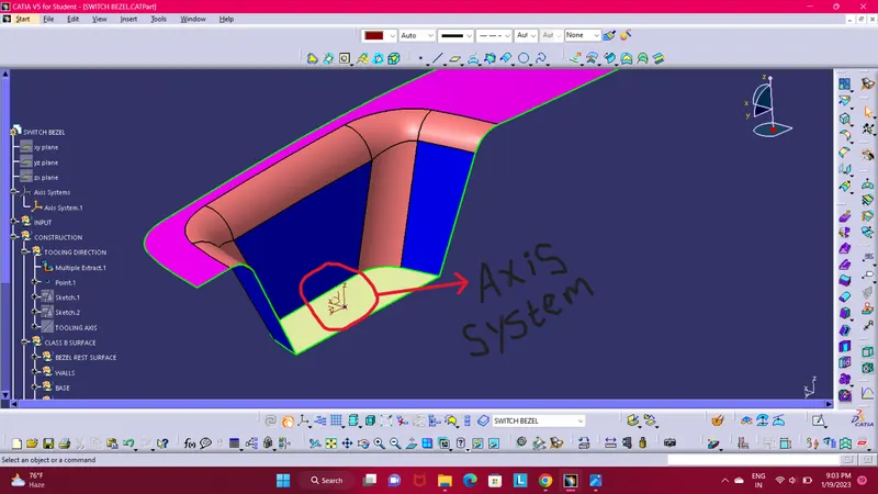
Axis System
- Then project the profile line of class-A surface to create a sketch on a yz plane of axis system draw two reference lines align to those incline lines as shown in below image.
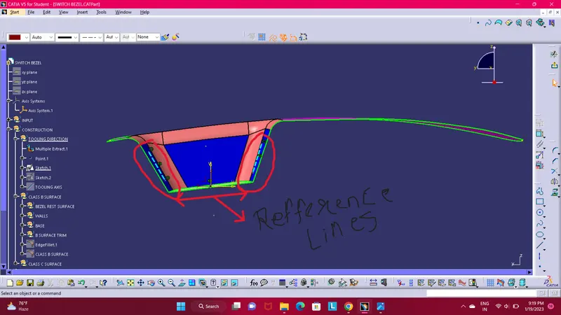
Refference Line
- Now create a tooling axis refferance line with the help of those two refference lines using the bisecting line command.
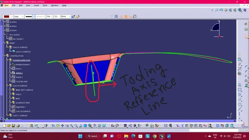
Tooling Axis Refference Line
- And then draw another sketch on zx plane using axis system and create a second tooling axis refferecne line by create a horizontally line give it 5 degree to another line as shown in image.
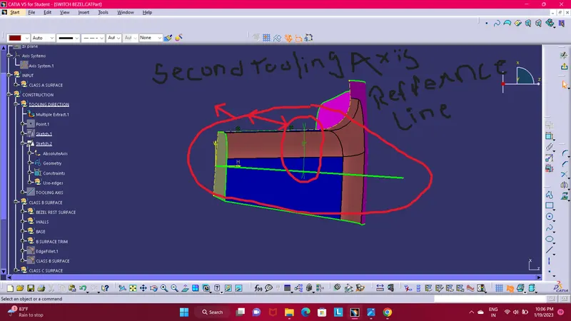
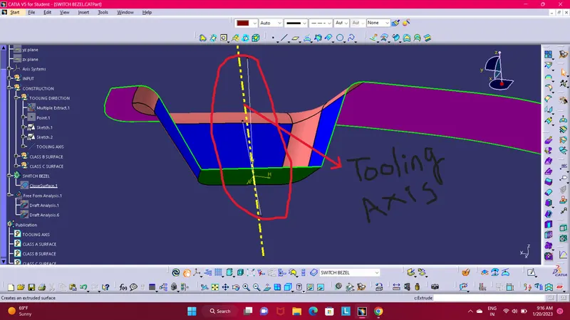
- Finally now create a Tooling Axis using those tooling axis refference lines lats we create by application of bisecting line command as shown in below image.
- Here i explain in steps how i complete the Draft Analysis creation.
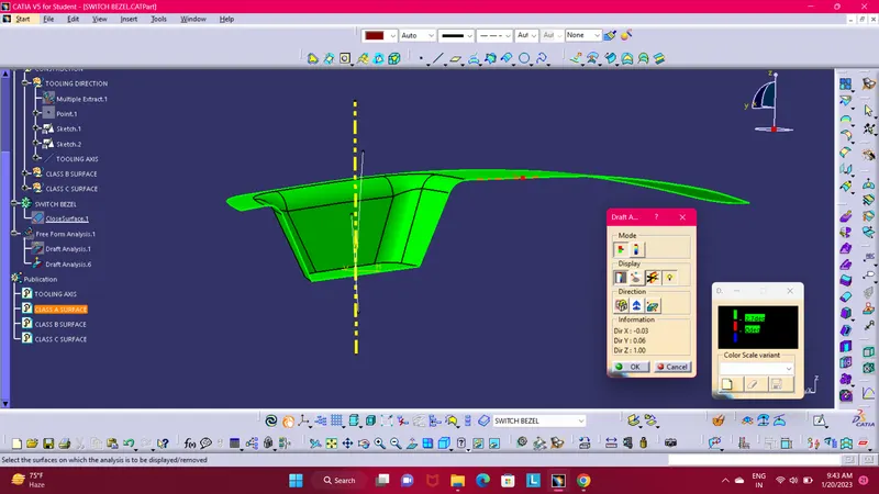
Draft Analysis
In the above image we are able to see the draft analysis of class-A surface. With the help of draft analysis command we can easly make draft analysis.
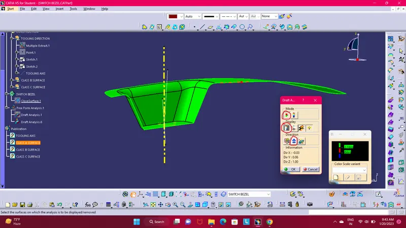
First apply a draft analysis command. From mode section choose first option as shown in above image highlight in red circle., then in display opt allow first opt to activate show/hide colur scale,
and the in last direction opt select the seconf opt compass then use fit all in command so you are able to see the compass as show in below image highlight in red circle.
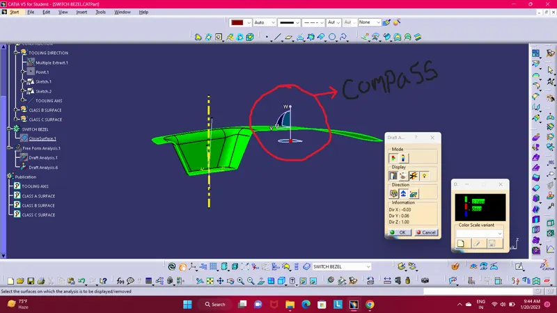
Compass
Then drag the compass to tooling axis and align to tooling axis line. Below the show alignment of compass and tooling axis image.
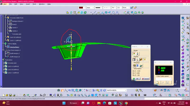
Compass Align to Tooling Axis
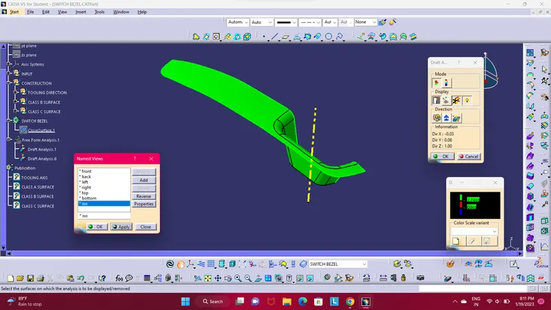
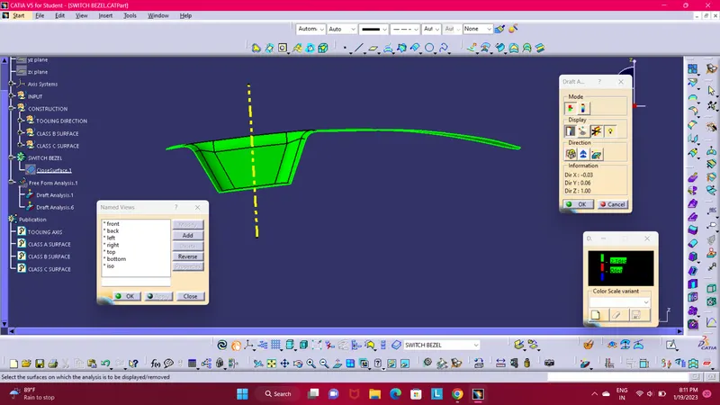
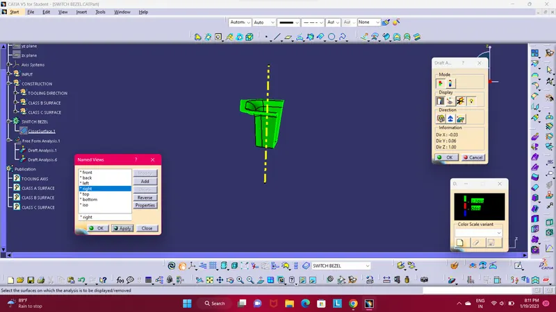
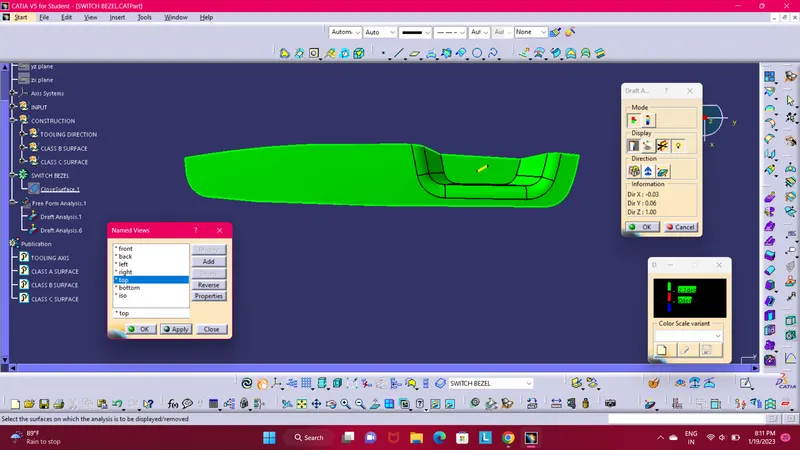
- Screenshots of the Draft analysis report for both the given Class-A surface and the final plastic component in various orientations (Isometric, Front, Side, and Top View).
ISOMETRIC VIEW.
FORNT VIEW.
SIDE VIEW.
TOP VIEW.
- Following are the screenshots of the Draft analysis report for the final plastic component in various orientations (Isometric, Front, Side, and Top View).
ISOMETRIC VIEW.
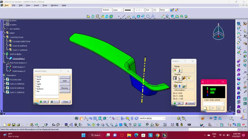
FORNT VIEW.
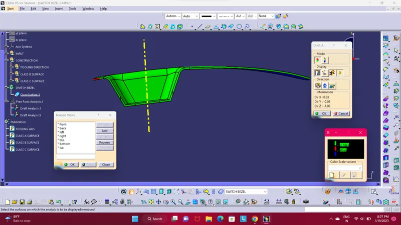
SIDE VIEW.
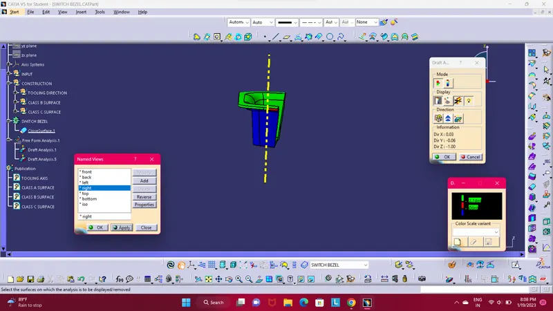
TOP VIEW.
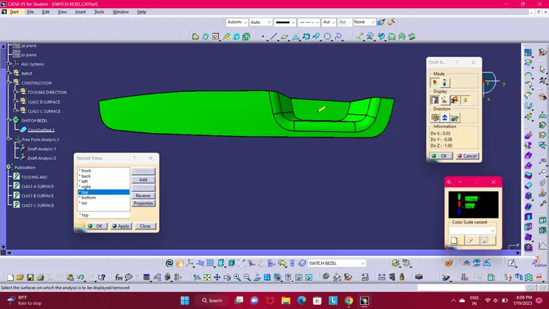
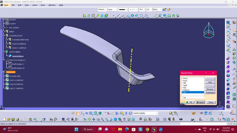
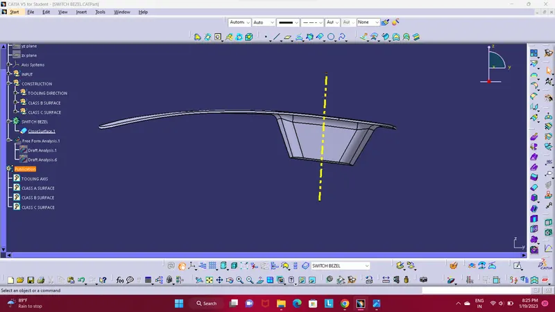
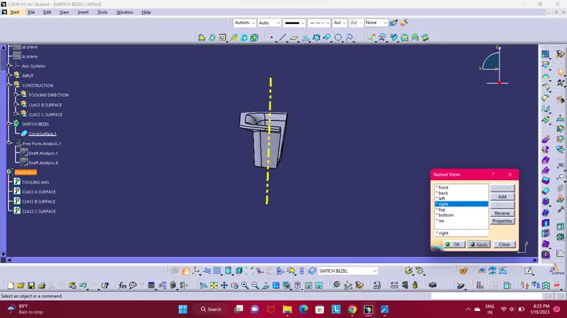
- Screenshots of the solid model with the proper color code of the draft angle in various orientations (Isometric, Front, Side, and Top View)
ISOMETRIC VIEW.
FORNT VIEW.
SIDE VIEW.
TOP VIEW.