Week 8 - Challenge 2 - Switch Bezel Design
Aim
The aim of this project is to develop the product design of the switch bezel with the help of the class A surface following the OEM standards.
Introduction
Class A
Class A surface is the term mainly used in automotive design industry. It describes the final production surface data for the aesthetic parts of the car.
Class B
Class B surface is the secondary surfaces which is not visible normally. These must be smooth and "error-free" as well, but are not held to the standards that class
A surfaces are.
Class C
Class C surfaces are the backside surfaces that can have tool marks, flash and other imperfections without hurting appearance, function, etc..
The steps involved in creation of this project are:
1. Bringing the class A surface of the switch bezel in Catia v5 software
2. Determining the tooling axis for the switch bezel
3. Creation of class B surface
4. Creation of class C surface
5. Joining all the class A, class B and class C surfaces of the switch bezel
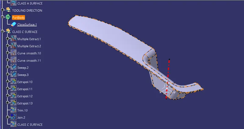
6. Building closed surface after joining all the surfaces
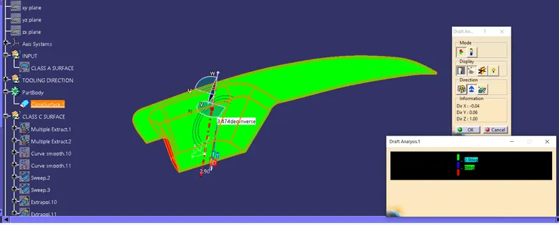
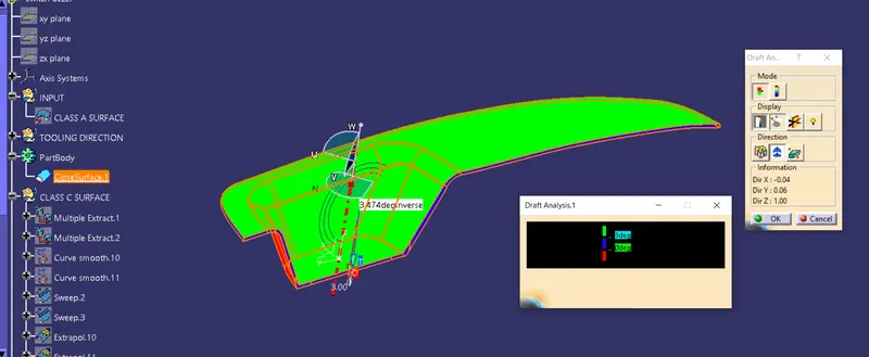
7. Draft analysis on the switch bezel
Procedure
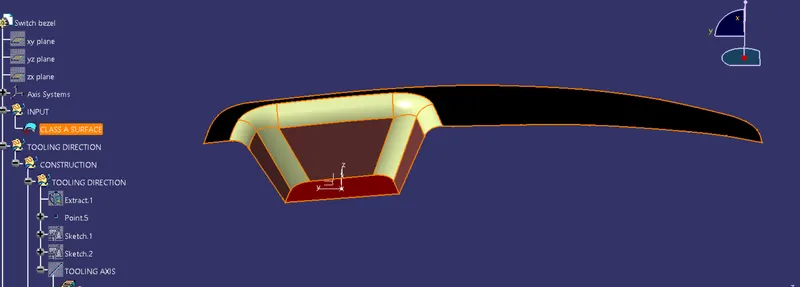
Below is the class A surface which was incorporated in the Catia V5 work bench to work upon
Determination of Tooling axis for the above class A surface
Sketches
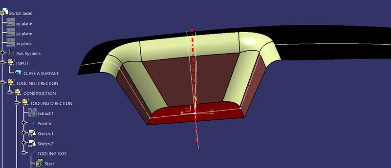
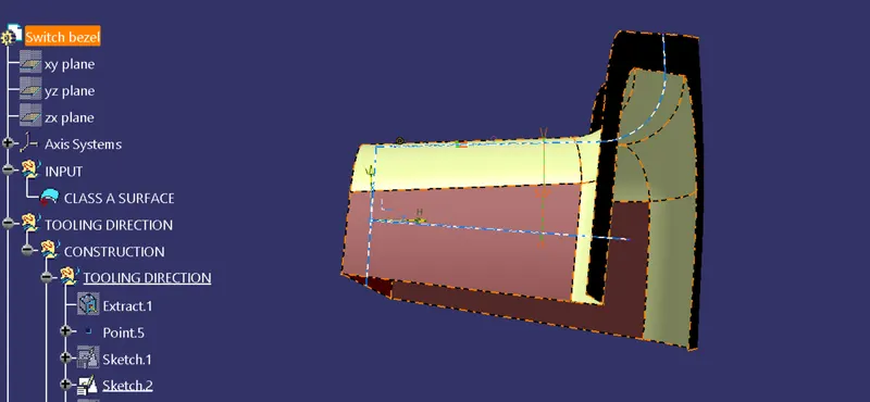
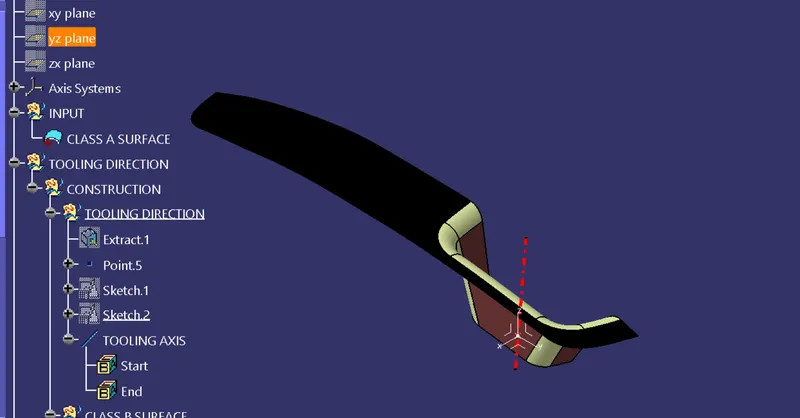
Main tooling axis:
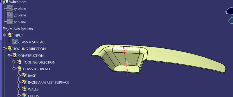
Creation of Class B surface
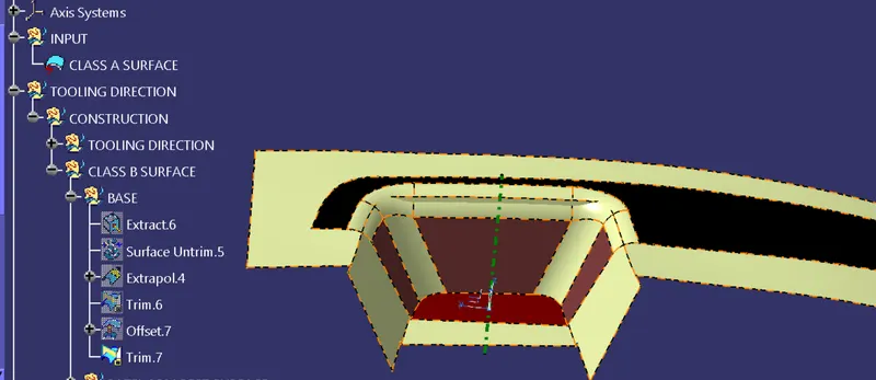
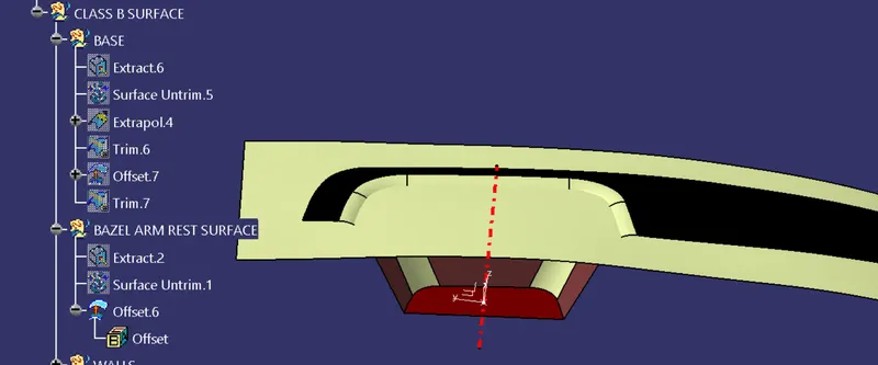
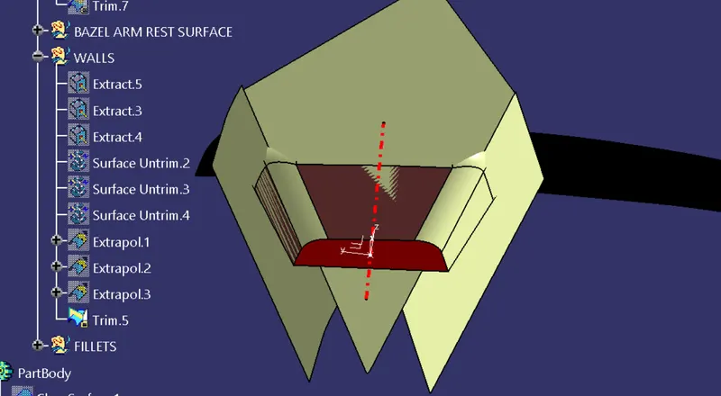
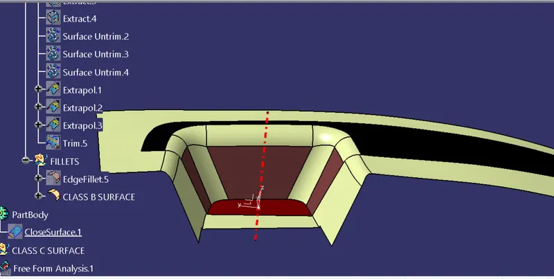
The class B surface is created by extracting each surface of class A surface and then untriming them.
After this an offset of 3 mm is given in the downward direction to generate the class B surface.
The surfaces are then extrapolated with a certain distance in order to create cross section among the surfaces to perform trim operation.
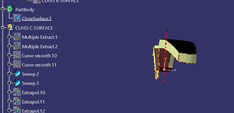
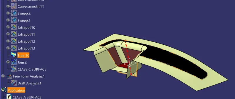
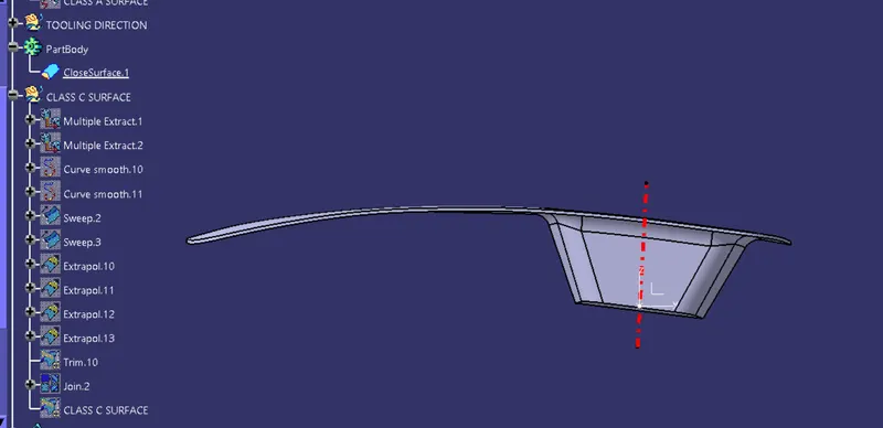
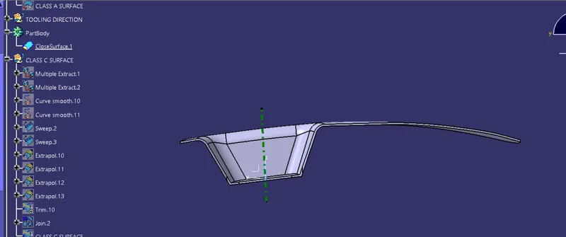
Creation of class C surface for switch bezel
For the creation of class B surface, first the boundary of the class A surface is extracted using Multiple extract feature.
After this sweep option is used to create the sweep along the tooling axis direction.