Advanced Sheet Metal Design Using NX Cad Challenge_2_Box Assembly
DESIGN OF SHEET METAL BOX ASSEMBLY
OBJECTIVE:
To design a Sheet metal Box Assembly using Siemens NX Sheet metal Application.
INTRODUCTION: Sheet metal is metal formed by an industrial process into thin, flat pieces. Sheet metal is one of the fundamental forms used in metalworking, and it can be cut and bent into a variety of shapes.
DESIGN METHODOLOGY:
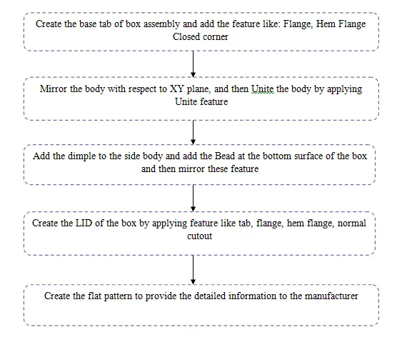
DESCRIPTION:
The function of different tools used in creating Sheet metal Box Assembly is as follows:
- TAB: Tab is only used in designing of sheet metal. It is a base where the flange is created.
- FLANGE: This command is used to add a flat flange to the bend portion of the casing. It consists of 2 region (Bend region Web region).
- CLOSED CORNER: It is used to modify two flanges in one operation and to close the corner where the two flanges meet.
- HEM FLANGE: It is used to modify an edge of a sheet metal part by folding it onto itself for the purpose of safe handling or to increase the edge stiffness.
- MIRROR BODY: This command is used to mirror the body created with respect to the plane selection.
- UNITE: This command is used to combine two bodies into a single body.
- DIMPLE: The dimple feature can be placed on any flat face including flanges and will extend in the direction of the face. Dimple dies are designed to reduce the weight in sheet metal fabrications, while adding strength and rigidity.
- BEAD: A Bead is a long, drawn out impression, which is impressed to increase stiffness in metal sheets or plates. It is also important that how the bead runs over the work piece.
- BREAK CORNER: It is used to round or chamfer sharp corners of a tab or flange.
- UNBEND: This is the next step followed while designing the sheet metal, the unbending is done to add other features like dimple, beads to the main face of the casing.
- NORMAL CUTOUT: Normal Cutout command is used to cut material by projecting a sketch onto the model and then cutting perpendicular to the faces intersected by the projection.
- REBEND: The rebending is the next step in the design of sheet metal where after applying the Bead features the Casing will be bent back to the original position in the reverse manner.
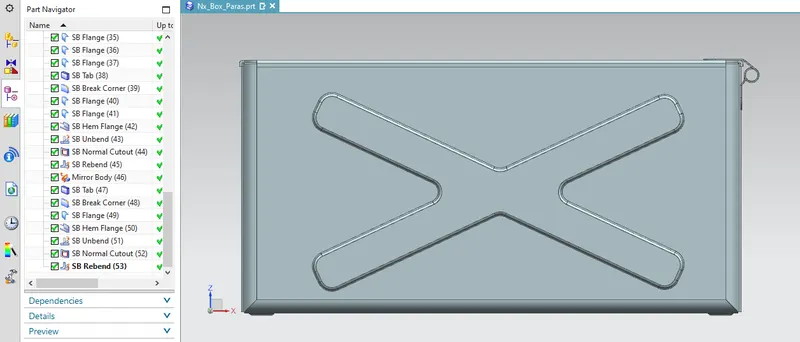
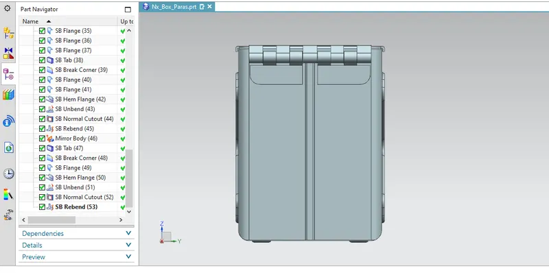
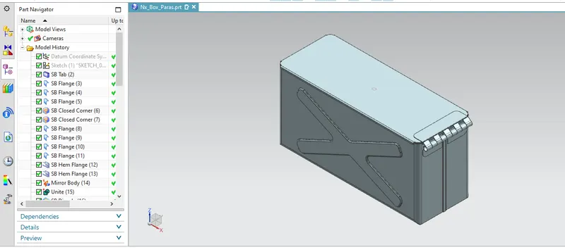
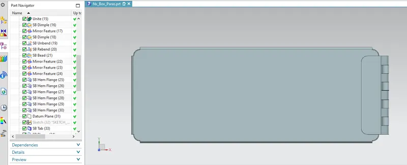
DIFFERENT VIEWS OF THE MODEL: The different rendered views of the Box Assembly are as follows:
FRONT VIEW:
SIDE VIEW:
ISOMETRIC VIEW:
TOP VIEW:
CONCLUSION:
Therefore the Sheet metal Box Assembly is completed by applying the required features at the required dimensions to the sheet metals.