Week 8 - Challenge 2 - Switch Bezel Design
Week 8 - Challenge 2 - Switch Bezel Design
OBJECTIVE
- To Design and Develop Class B and C Surfaces from the given Class A surface
- With Create Prossible Tooling Axis
- To Analyse the solid component (Combine Class A,B and C) in Featured Draft analysis with Guiding Reference of Tooling Axis.
Class A Surface
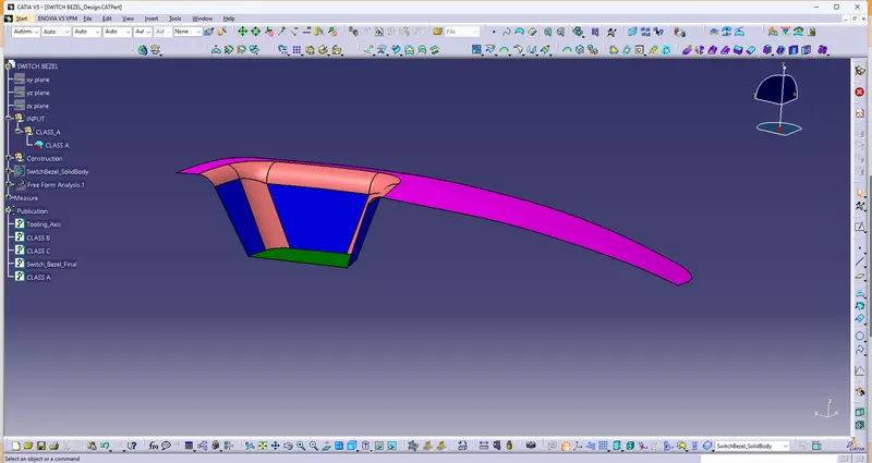
Screenshot of given Class A Surface
Tooling Axis
- From the Given Class A surface, to determine the possible direction of component to draft
- Extract Base of the surface (No propagation)
- Point is created on the base of the surface
- then add Axis System on the ref.point
- Along this axis system YZ direction Positioned sketch as to construct
- Intersection of the surface along YZ direction,inclined Edges of intersection sketch two Lines
- from these two lines create a Bisecting Lines of YZ Direction
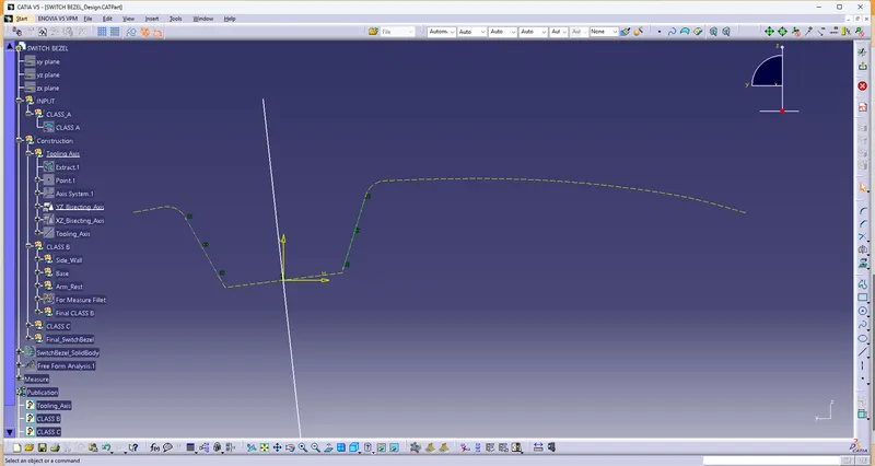
Screenshot of YZ Bisecting Line
- To create XZ direction Bisecting Axis of the surface, by positioned sketch
- Compare to YZ Direction, XZ direction have a one side of face to intersect
- By intersection on XZ Direction, One side of Inclined edges create line and
- then create line on the axis system projection point (Ref.Point) and constraint to the angle of 3 degree from the Intersection line.
- And the line as considered Bisecting Line of XZ.
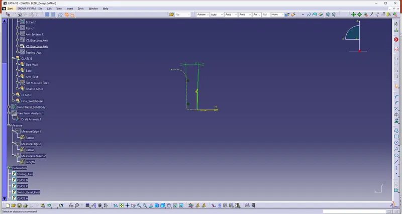
Screenshot of XZ Bisecting Line
- Both YZ and XZ Bisecting Lines, Create Bisecting Line as Tooling Axis of the component to develop Class B and Class C.
- then also Featured Draft Analysis as to derive along this Tooling Axis.
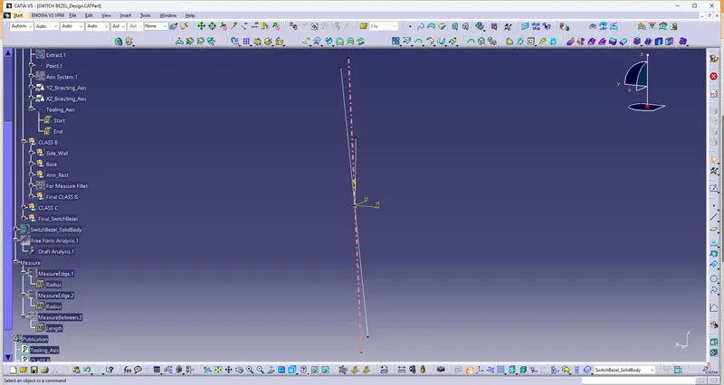
Screenshot of Tooling Axis of the Component
Class B surface construction
Side Walls
- Extracts side Walls of the Class A Surface (No Propagation).
- Then Untrim those walls and extrapolate in point continuity (Propagation) with distance of 50mm.
- Trim all the Walls and Offset through outward of 2.5 mm (Because of thickness of the component is mentioned 2.5mm).
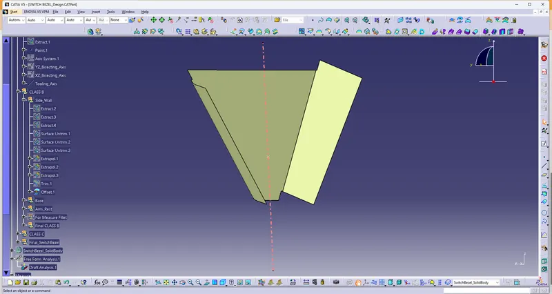
Screenshot of Side Wall surface
Base
- Extract Base of the Class A surface and Untrim the base
- ExtraPolate the base distance of 50mm (Point Continuity - Propagation)
- Offset the base through downward of 2.5mm
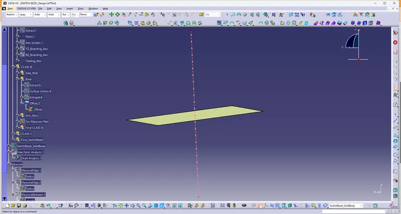
Screenshot of Base Surface
Arm Rest
- Extract the arm rest from the Class A surface and Untrim
- Offset the arm rest surface downward Direction of 2.5mm.
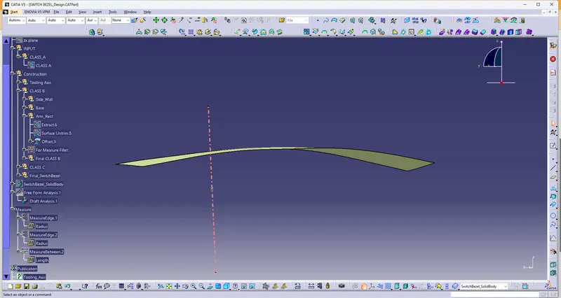
Screenshot of Arm rest Surface
- Trim all Side walls, Base and Arm rest surface and Edge Fillets are created
- On Filleting the Class B surfaces, to considered the Thickness of the component 2.5mm
- For Inward Fillet,Radius of the curve is 14mm minus the Distance of Class A to Class B 2.5mm and Resultant fillet radius is 11.5mm
- For Outward Fillet, Radius of the curve is 15mm Add the Distance of Class A to Class B 2.5mm and Resultant fillet radius is 17.5mm
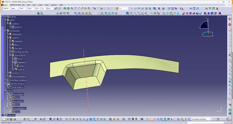
Screenshot Of Class B Surface
Class C Construction
- From the Class A surface, Create Boundary of the surface
- Then Using Sweep command, Create Class C surface at 3 degree of Draft angle and distance of 20mm in the Tooling axis Direction.
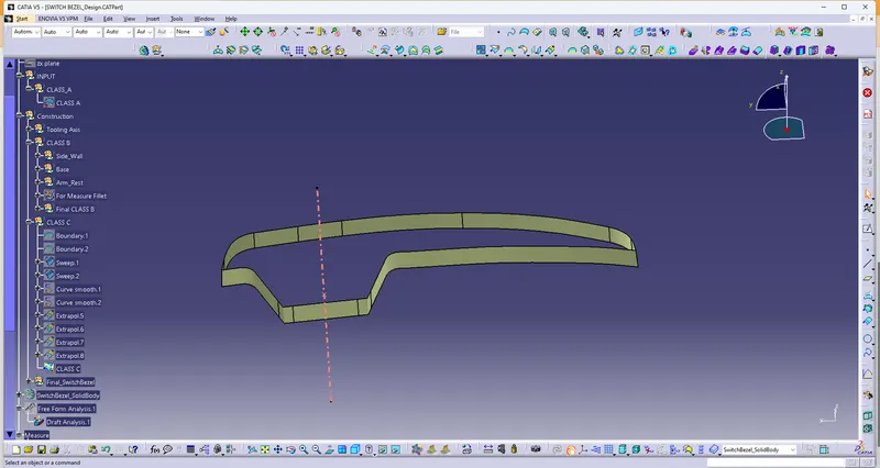
Screenshot Of Class C surface
Final of Switch Bezel Construction
- Join both Class A and Class C
- Then Trim both Join (Class A & C Surfaces) and Class B.
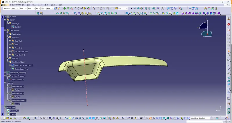
Screenshot Of SwitchBezel Surface (Class A,B and C Combine)
Draft Analysis of Class A Surface
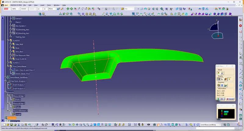
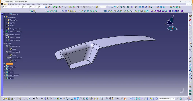
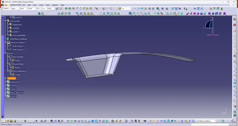
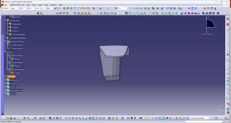
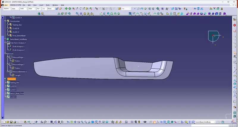
Screenshots of the solid model with the proper color code of the draft angle in various orientations (Isometric, Front, Side, and Top View)
Isometric View
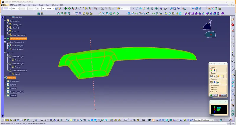
Front View
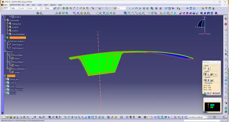
Side View
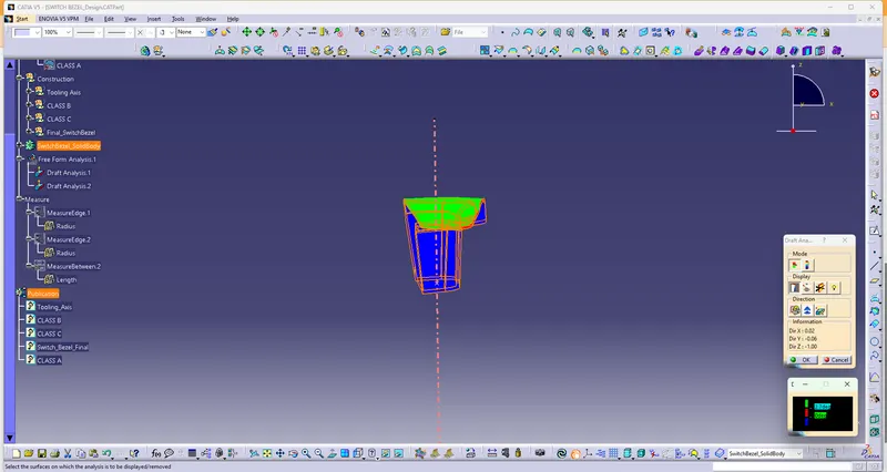
Top View
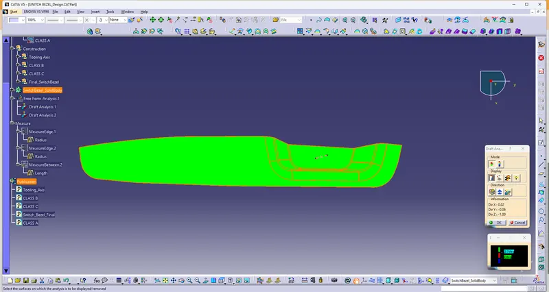
Solid View of Switch bezel