Week 8 - Challenge 2 - Switch Bezel Design
Aim :
To create a switch bezel component using input of Class A surface.
Objective
The objective of the project is to design the switch bezel and to do a draft analysis for it by creating the required tooling direction with the help of Bisecting method
Introduction
The control panel bezel is the frame part of the window switch that holds its switch covers and buttons into a place. moulding is the method used to manufacture the plastic trims of an automotive by most OEM's hence by considering the manufacturing consideration the switch bezel is designed.
Input given : Class A surface.
Thickness : 2.5mm
Draft angle : Min 3deg
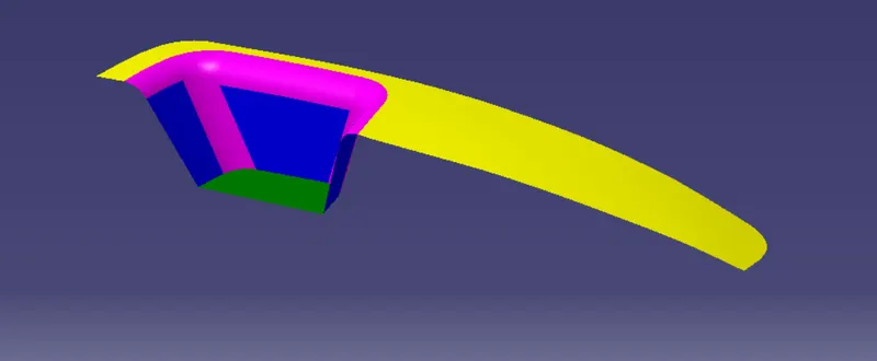
Class A surface.
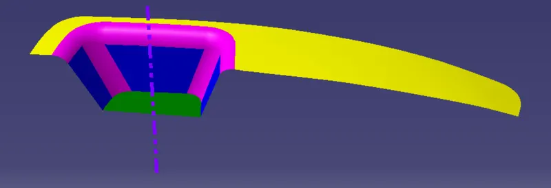
Tooling Direction :
Class B Surface :
Creation of Class - B surface
1. For creating the class - B surfcae the required surface except the offset surface have been extracted and then untrimmed all the surface.
2. Then all the surfaces have been extrapolated to get intersections between them.
3. Since the thickness of the Switch bezel is 2.5 mm the B- Surface was offset to 2.5mm and the required trim operations must be carried out.
4. Finally, the required corners have been filleted 12.5mm ( 15mm-2.5).
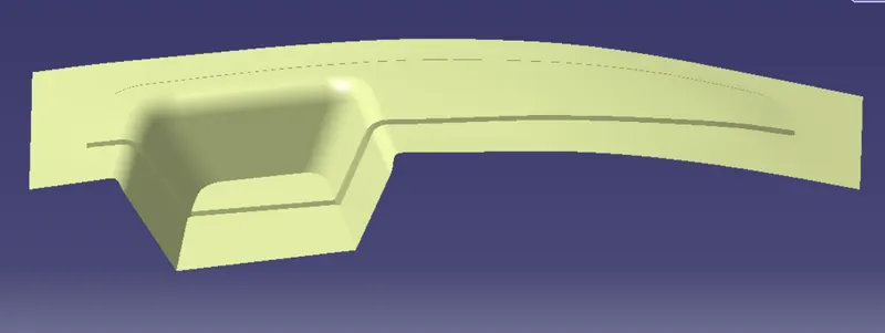
Class C surface :
Creation Of Class - C surface
1. The requred outer edges of the A- surface were extracted using Multiple Extraxt. Then for avoiding the patches the curve is smoothened using the curve smooth option.
2. Then by using the sweep command the surface was created with following feature controls.
Profile type - line
Subtype - With Draft direction
Guide curve - smooth curve
Draft Direction - Tooling axis
Draft computation Mode - Square
Angle - 3 degree
Angle Sector - Positive Downwaed
Length - 20mm
3. Then by using extrapolate command the edges were intersected between the surface corners which eases the trimming operation
4. Now the requred portion of the c - surface were trimmed out.
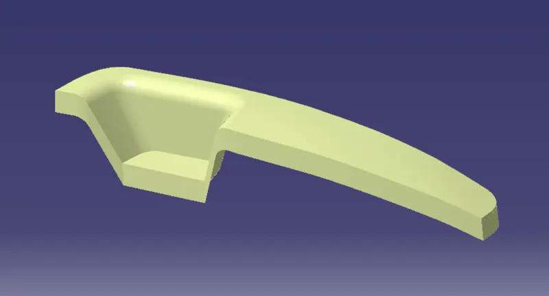
Part Body : SWITCH BEZEL
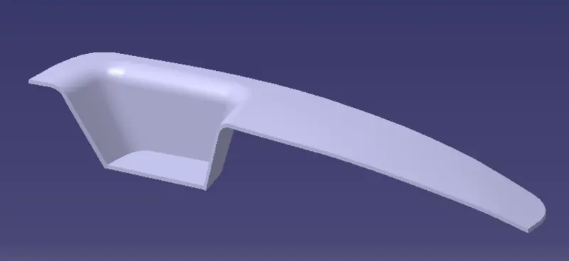
This is the final component created using class A surface with 2.5mm of thickness.
Isometric view
Side view
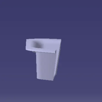
Front view
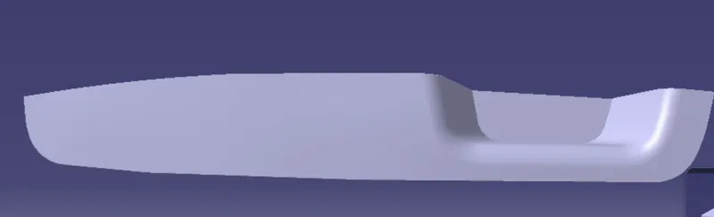
Front view

Creation Of Closed Surface
1. Now the class - A and Class - c surfaces were joined together by removing the gaps in between them with the help of extrapolation ( tangent continuity ) and trim surface
2. Then the exact surface of the switch Bezel was trimmed from the above - resulted trim surface with the class - b surface.
3. Then by defining the part body by using the closed surface command ib Part Design, the component's solid body is created.
Conclusion
Finally the Class - A , B& C surfaces with the tooling direction have been publised and the switch bezel is moved on to the
designing of the next operation - the creation of B - side features.