Week 8 - Challenge 2 - Switch Bezel Design
AIM
To create a Switch Bezel Plastic Component through a given Class A Surface and perform Draft Analysis on the final plastic component.
OBJECTIVE
- To make sure that the model meets the requirements of the draft angle.
- To create the Tooling axis using bisecting method.
- To perform Draft analysis on the given Class A Surface.
- To create the required Class B and Class C surfaces.
- To obtain a solid body from the surface using Close Surface feature.
- To perform draft analysis on final plastic component.
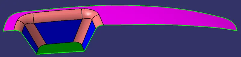
CLASS A SURFACE
- Class ‘A’ surfaces are primarily used in the automotive environment and refer to those surfaces which are visible in a product. In other words: A - class surfaces are those aesthetic/free-form surfaces, which are visible to us (interior/exterior), and have an optimal aesthetic shape and high surface quality.
- The surfaces or regions which are visible nowadays are considered for Class-A modelling. It is one of the reasons why the importance of Class-A modelling is increasing day by day. Majority of the time this term is used in Plastic Part designs.
CLASS B SURFACE
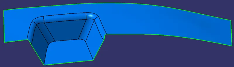
- The Class B surface is created from the Class A surface, keeping the thickness of the component in check.
- The Class B surface resembles an offsetted surface from the Class A.
CLASS C SURFACE
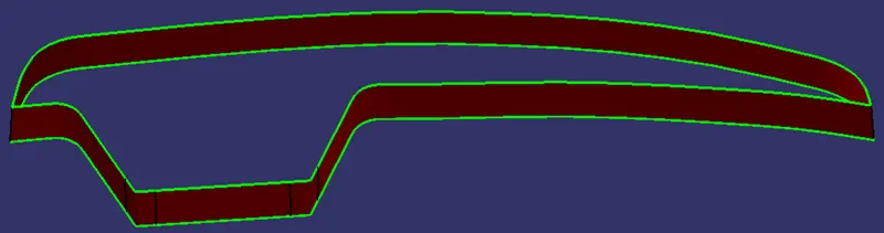
- The Class C surface is used to bind the Class A and Class B surface together in order to form a closed surface.
PROCEDURE
Creating Tool Axis
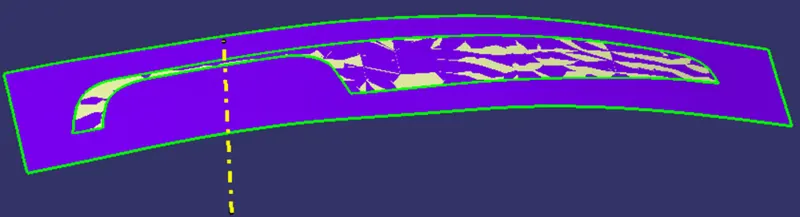
- Initially the given Class-A surface was imported and checked for any discrepancies in the boundary and performed draft analysis on it at 3-degree draft.
- The ejection from the mould after manufacturing the interior trim must have the nominal 3-degree draft angle.
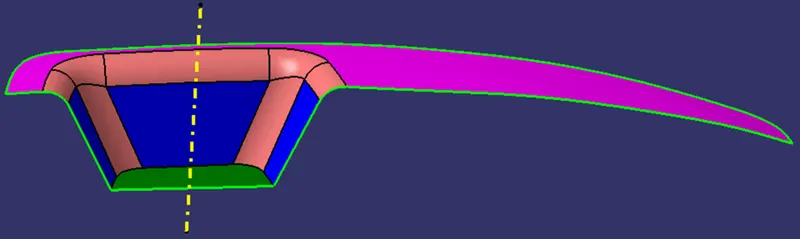
- Hence the tooling directions created by considering the above factor and bisecting method is used.
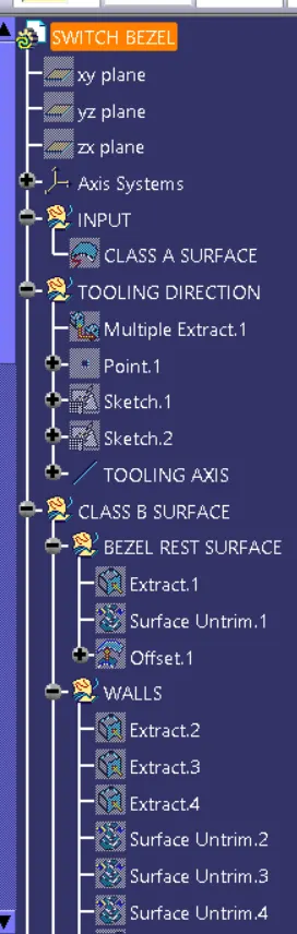
- The base surface of the class-A was extracted to create a reference point on the surface using the point, create a line in the z-direction and an axis system was inserted to the point.
- Then using projection intersection along the yz-plane is created and the two inclined lines were drawn inside the positioned sketch.
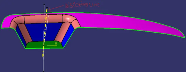
- Then bisecting lines with the two inclined lines were created.
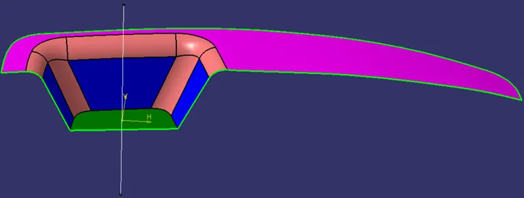
- Now the same procedure is done along the xz-plane but on xz plane, we only have one surface line so the centre point is used to extrude a line along the z-direction and gave a measurement of 6 degrees from the surface line.
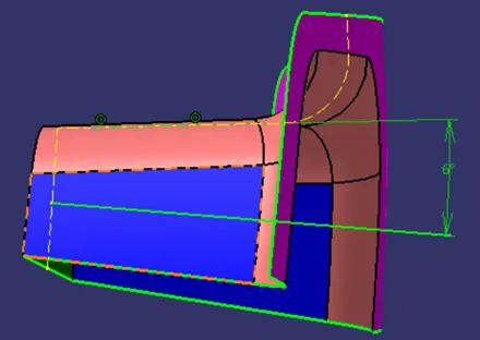
- Bisecting these two lines sketch1 and sketch2 the bisecting line is created and published as a tooling axis.
Creating Class B surface
- Initially the class A surface is divided into 3 sections- Bezel rest surface, walls, base.
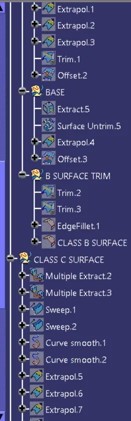
- Then all the surfaces have been extracted, untrimmed and extrapolated one by one to get intersections between them.
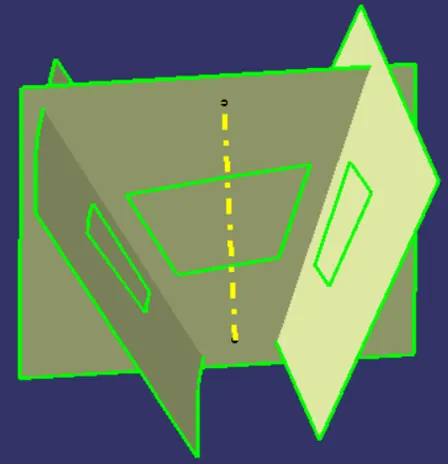
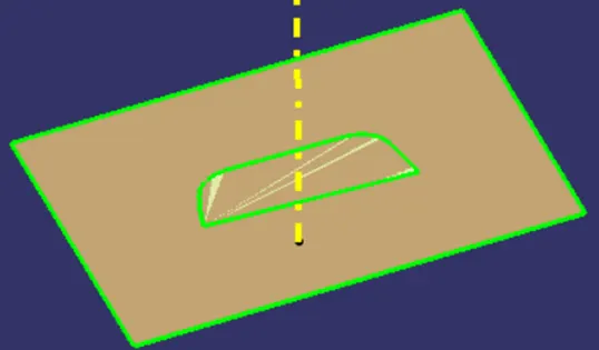
- Since the thickness of the Switch bezel is 2.5mm, all the surfaces were offset to 2.5 mm.
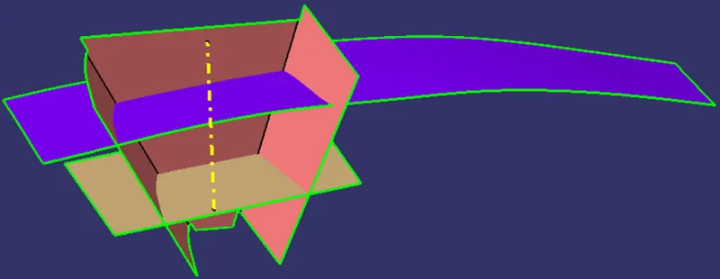
- once all the surfaces are created (i.e., bezel rest surface, walls, and base surface). The required trim operations were performed to form a class-B surface.
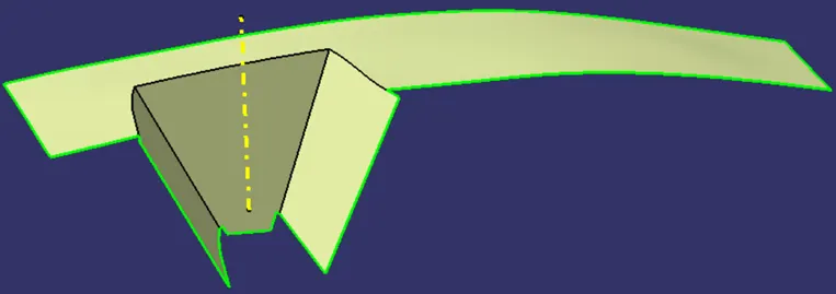
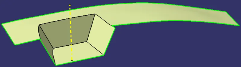
- To Perform the fillet operation. Fillet value should be calculated from the Class A surfaces for every edge in the B surface.
- Finally filleting the edges of class B surface considering thickness value to it.
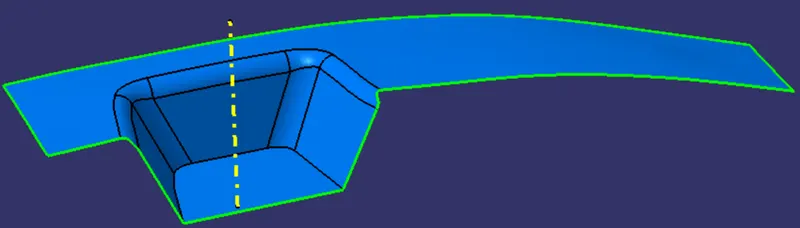
- The fillet value should be calculated to ensure the component has a uniform thickness.
Creating Class C surface
- The required outer edges of the A-Surface were extracted using Multiple Extract. Then for avoiding the patches the curve is smoothened using the Curve Smooth option.
- Sweep operation is performed (with draft direction) selecting the smooth curves as the guide curve and tooling axis as the direction and draft angle as 3-degree.
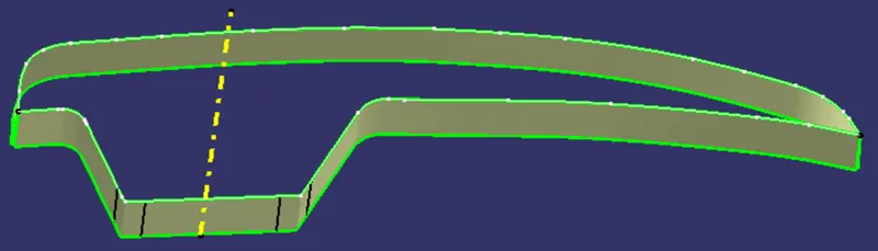
- Then by using extrapolate command the edges were intersected between the surface corners which eases the trimming operation.
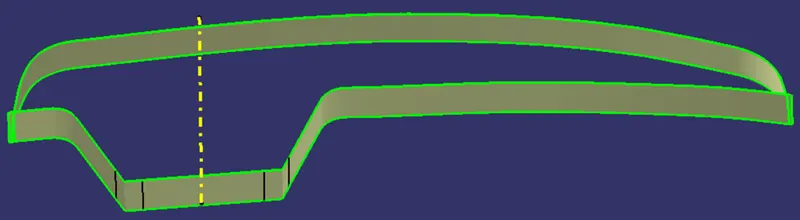
- Now the required portion of the C – surface was trimmed out.
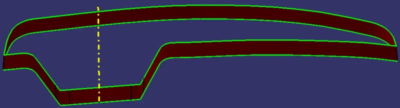
- Join class-A and class-C surfaces. Make sure that there is no unnecessary boundary present, if there, then increase the merging distance (not more than 0.003mm) and even after there is some unwanted boundary, extrapolate class-A by a small distance and trim it with class-c instead of joining them.
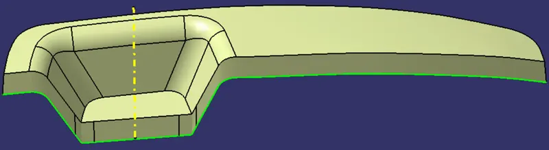
Creating Solid Body
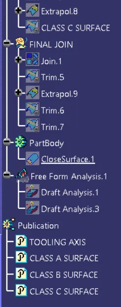
- Later, CLASS C and CLASS B surfaces were trimmed and forms the switch bezel surface.
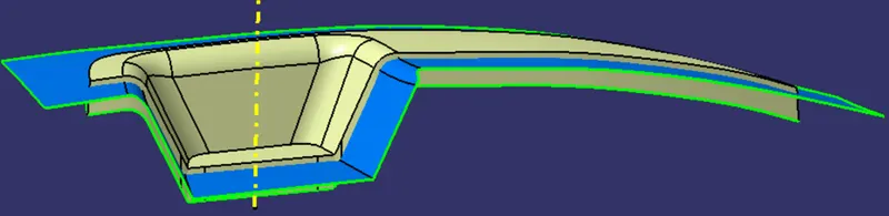
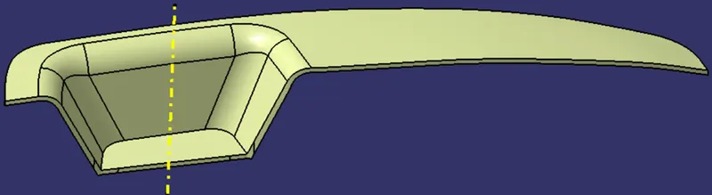
- Using the surface created, the solid component was obtained using the Close surface feature present in the part workbench.
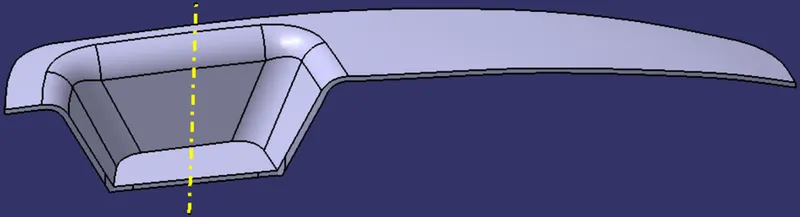
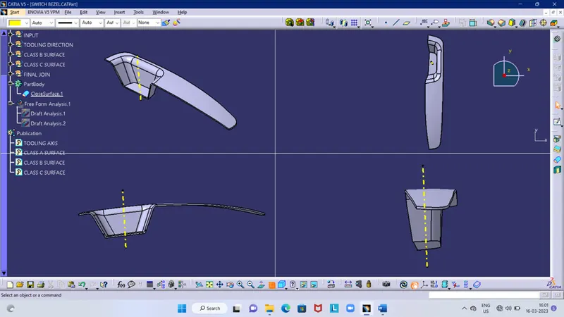
- The Tooling axis, Class A, B and C surfaces were published.
DRAFT ANALYSIS
- First, we should change model into material mode.
- Go to insert and in analysis select feature draft analysis.
- Align the compass along tooling axis and lock it.
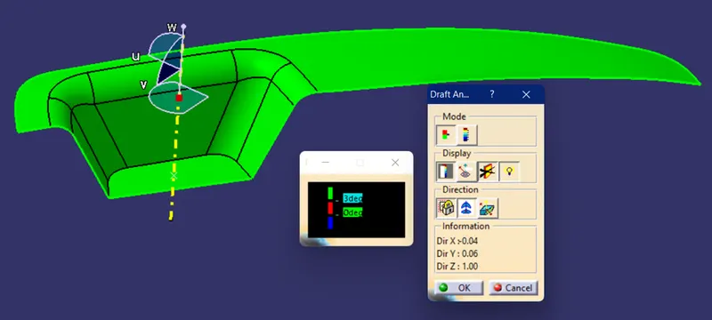
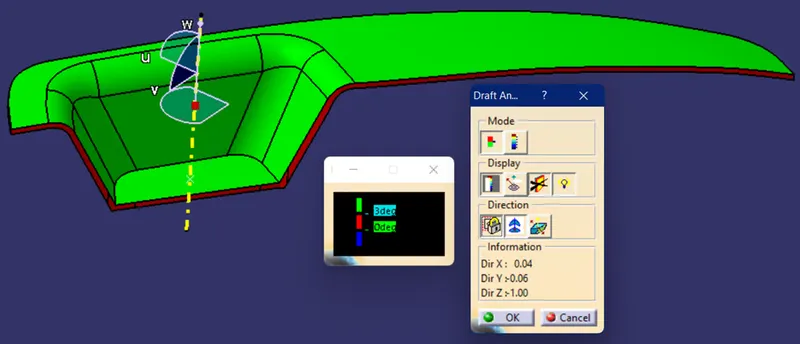
- Next click on the surface and see that the surface is within the permissible limit of the values.
- The green colour area shows that it satisfies the 3-degree draft angle. If not satisfied then by using the Running point tool the area is measured and then altered to get a successful draft for the created tooling direction.
On given Class A surface
On obtained PART BODY
EXPANDED TREE STRUCUTRE
CONCLUSION
- The creation of Tooling axis and Draft analysis were performed.
- The solid component was created from the surface geometry.
- The necessary screenshots and files were attached.
- The Class A, B, & C surfaces and also the Tooling Direction have been Published.