Week 8 - Challenge 2 - Switch Bezel Design
WEEK 8 - CHALLENGE 2 - SWITCH BEZEL DESIGN
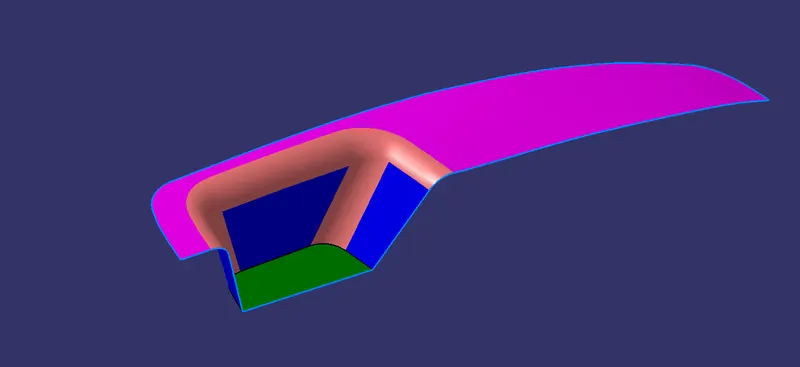
AIM : To create the Switch Bezel Plastic component through the given Class-A surface. To begin with, the tooling axis for the given Class-A Surface should be created meeting the requirements of the draft angle and at the end perform the Draft analysis on the model.
Take the Thickness of the component to be 2.5 mm
GIVEN CLASS A SURFACE :
IMPORTANT NOTE :
- Tree Structure
- Ensure Proper Tree Structure
- Geometrical sets should have a proper name based on the sketches present inside of it
- All the sketches should be created under the Geometrical set
- Use the Close Surface feature to make a solid body from the surface.
- Publications: Use the publication option and publish the below
- Tooling Axis
- Class A, B, and C surface
SWITCH BEZEL DESIGN IN CATIA V5 :
TOOLING AXIS CREATION :
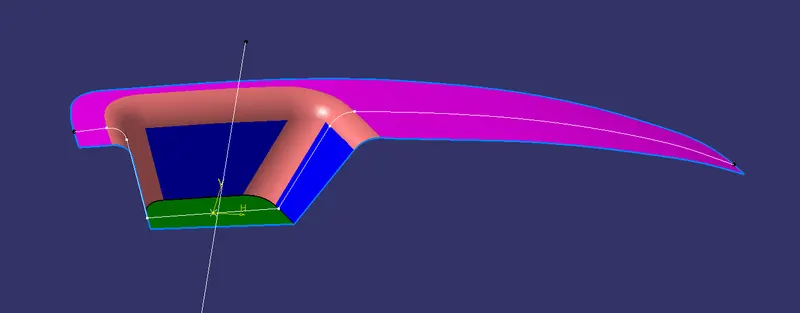
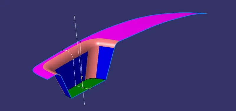
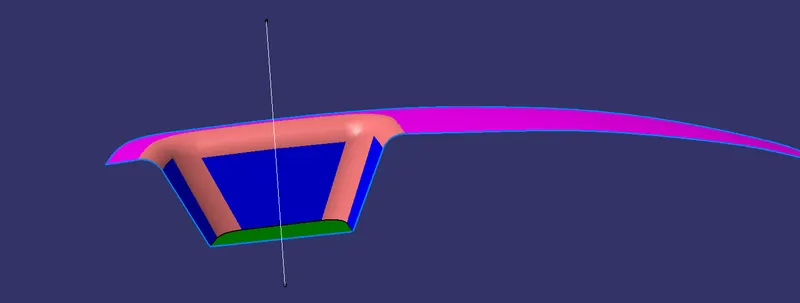
Creation of Tooling Axis :
- Initially extract the base surface for point creation, after make the axis system on that point.
- Next step is make intersection curve on YZ plane to make bisecting curve in by sketch positioning tool.
- Next same as the making the intersection curve on given class A surface on by using the ZX plane, next is make the same as thebisecting curve in sketch positioning tool.
- Next is make the bisecting line between the two two lines of two sketches i.e., Tooling Axis creation.
DRAFT ANALYSIS OF CLOSURE SURFACES OF A,B,C :
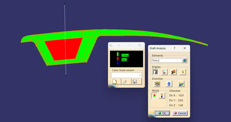
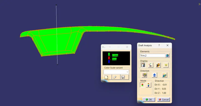
In the draft angle direction 2.2 degrees makes the proper assembling of the part to part and 3 degrees causes the negative improper draft direction and i make the 2.2 degrees is the proper tooling of this part.
CLOSURE SURFACE OF SWITCH BEZEL IN CATIA V5 :
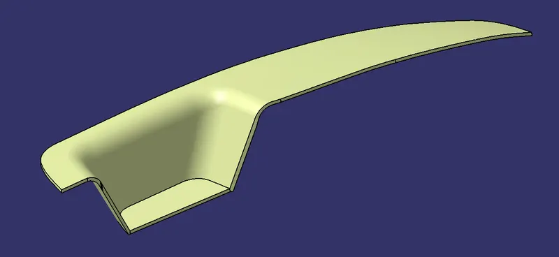
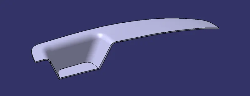
- Isometric View :
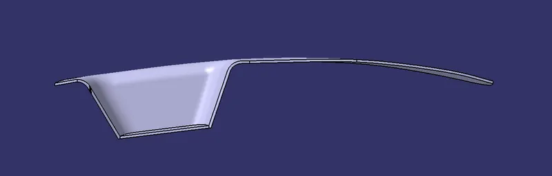
- Back View :
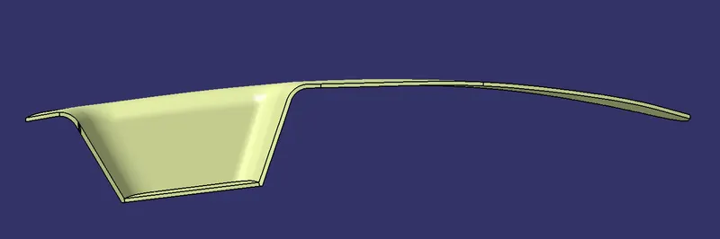
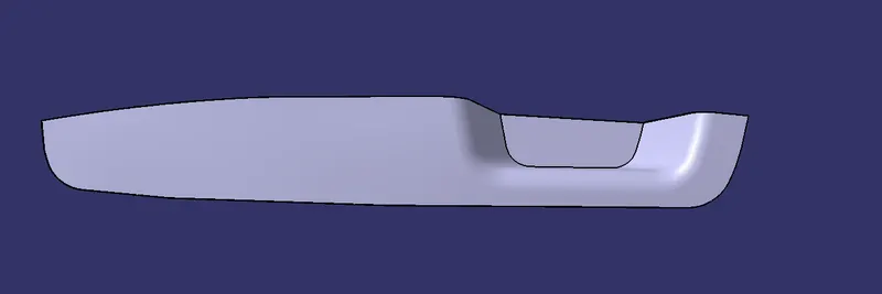
- Top View :
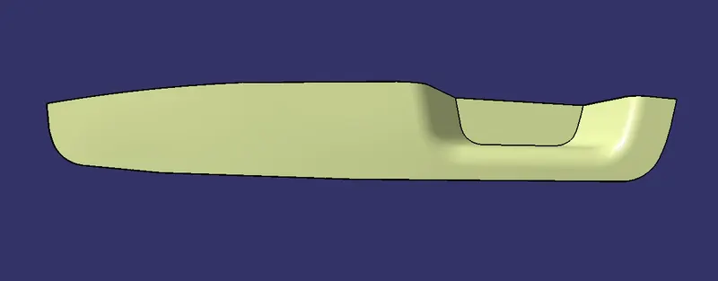
SOLID CATPART DRAWN IN CATIA V5 :
- Solid Part of Closure surface of Switch Bezel Different views :
DRAFT ANALYSIS OF SOLID CATPART:
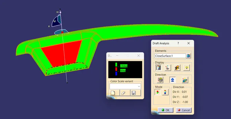
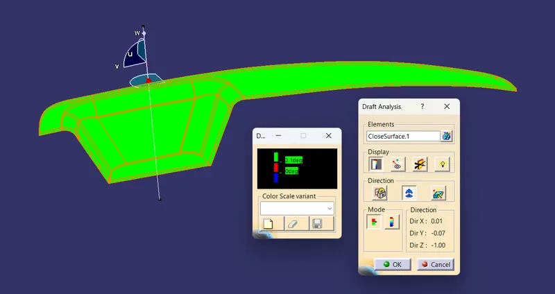
In this solid cat part 2.1 degrees makes the proper tooling direction of this part.
CONCLUSION :
Hense created the Switch Bezel Plastic component through the given Class-A surface. To begin with, the tooling axis for the given Class-A Surface should be created meeting the requirements of the draft angle and at the end perform the Draft analysis on the model.
Solid Part of Thickness of the component to be 2.5 mm is created.