Week 8 - Challenge 2 - Base Bracket Design
BASE BRACKET
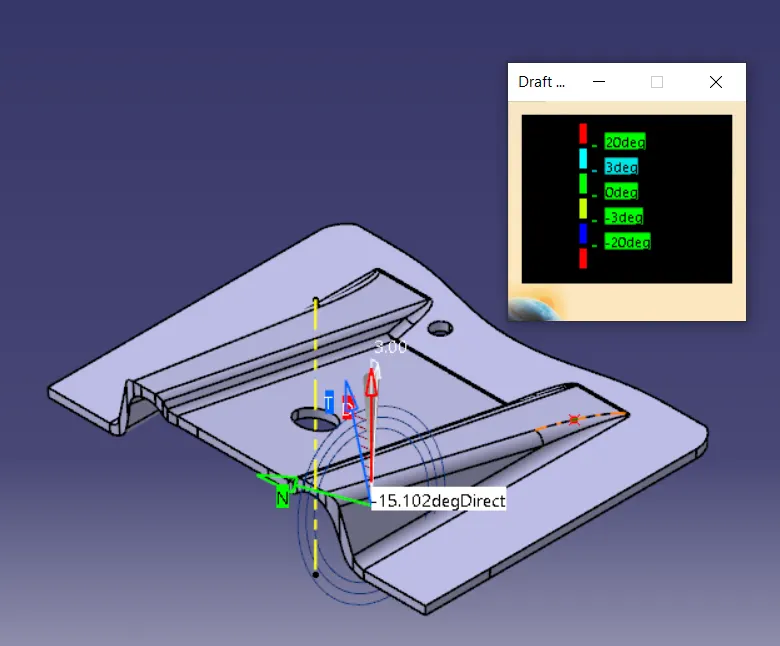
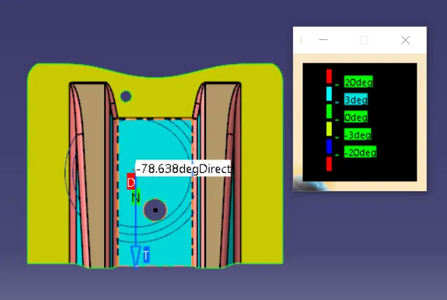
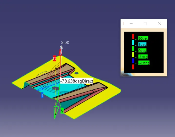
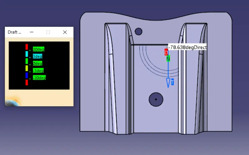
Steps for specifying tooling axis:
- Use Join command and confirm that surfaces are joined together properly with no gaps.
- Analyse the surface model and decide the best tooling direction.
- Create a point at the center, and create axis system at that point.
- Draw the line from that point and name it as dummy tooling axis.
- Intersect the point created and class-A surface, get the boundary line at the intersection.
- Create the two lines from the angled line on the either sides.
- Create a bisecting from those two lines, name it as a Clearing axis in Y-direction.
- Intersect the point created and XZ plane get the boundary line at the intersection.
- Create a line from that point, name it as a Clearing axis in X-direction.
- Create the bisecting line from the obtained two bisecting axis.
- Now name it as a Tooling axis which is required axis for the tool passing.
Feature Tree:
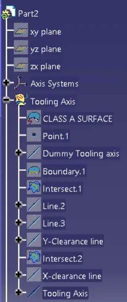
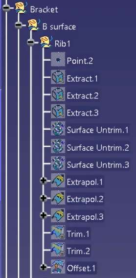
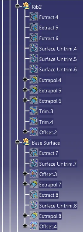
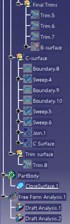
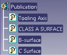
Class-A Surface Images:
Front View Side View
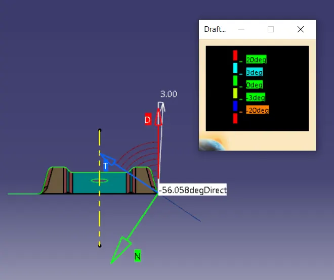
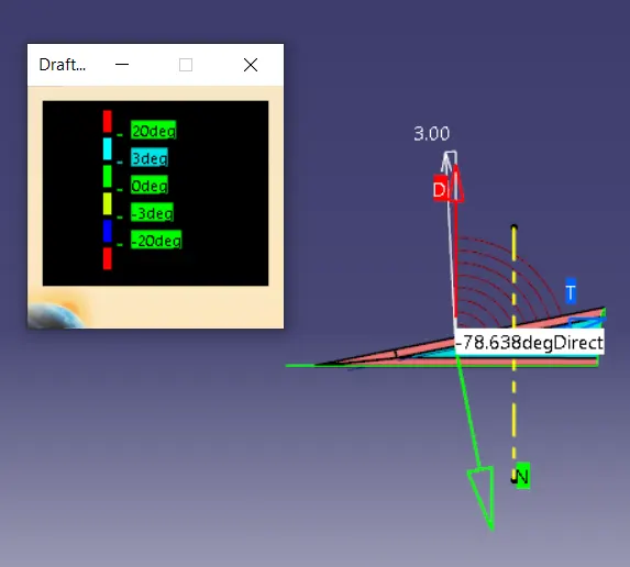
Top View Iso View
Solid-Plastic Part Images:
Front View
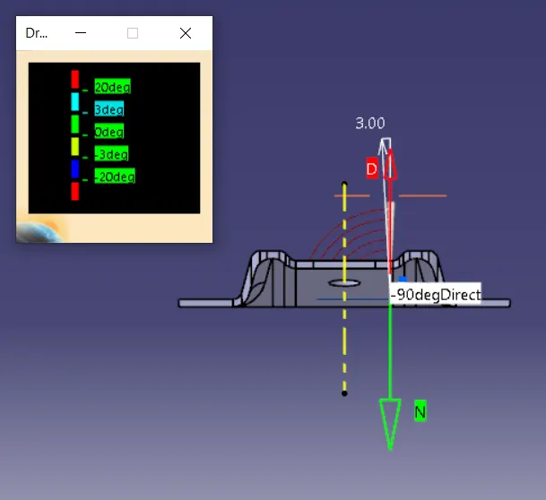
Side View
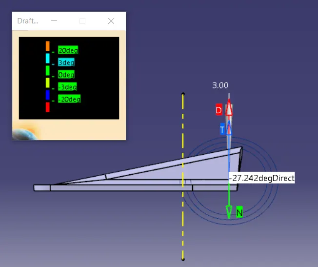
Top View
Iso View