Week 8 - Challenge 2 - Base Bracket Design
Aim:
From the given base bracket component create the tooling axis and the class A,B and C surface.
Procedure:
This is the component given for the operation. In this component at first dummy axis is made with selecting the hole and making the point with the point an line is made.
After that an plane is created along yz direction and made the intersection line. After the intersection line the points on the intersection line is selected and created an line. With the line type changing into bisecting and select the two line created and the point there creates and tooling axis at the centre.
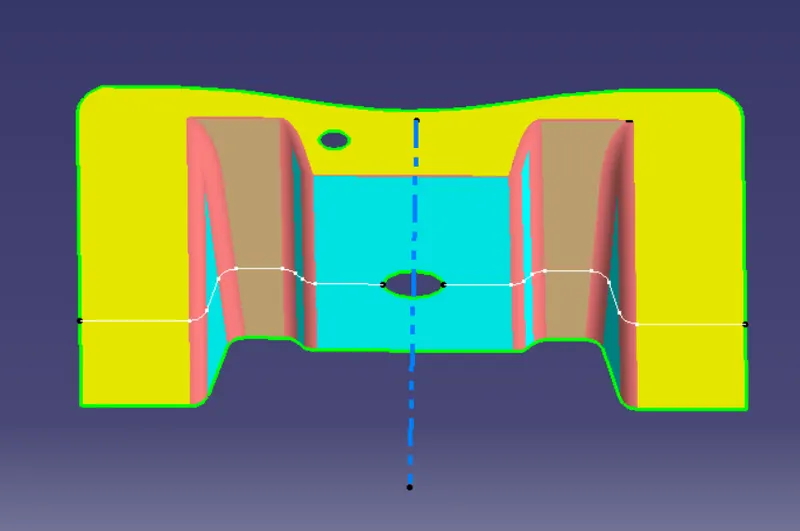
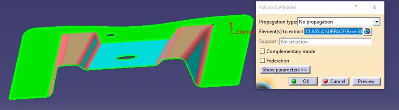
After completing the tooling axis, extract the base bracket plastic component for further processing it is used for creating the surface B. Extract like given in the image.
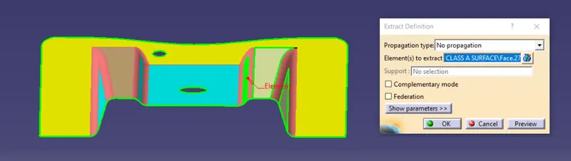
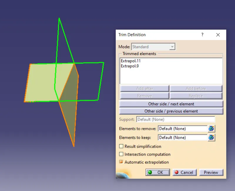
After extracting hide the class A surface and the part is shown. Now selecting all 3 parts untrim all the parts after that extrapolate the surface by clicking on the line and the surface and change the propogation mode into point continunity. All the 3 parts are made like this.
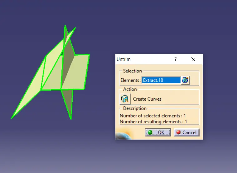
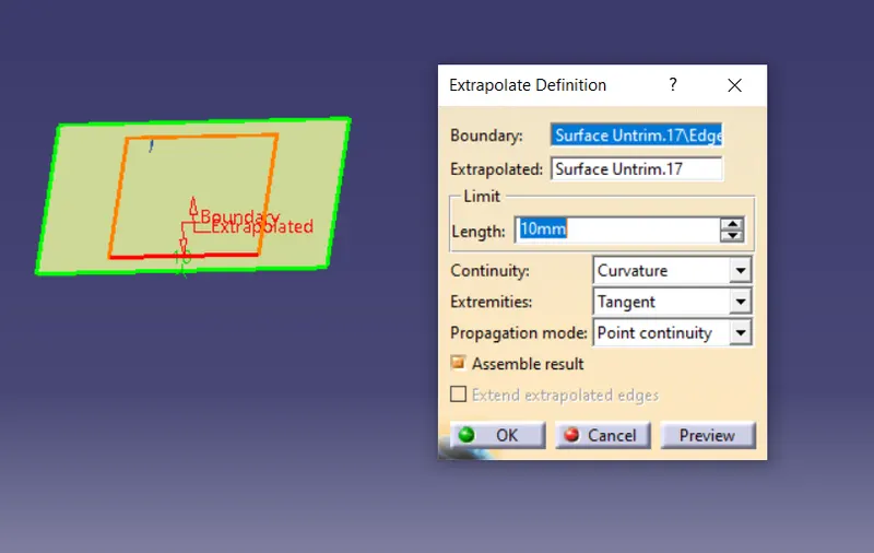
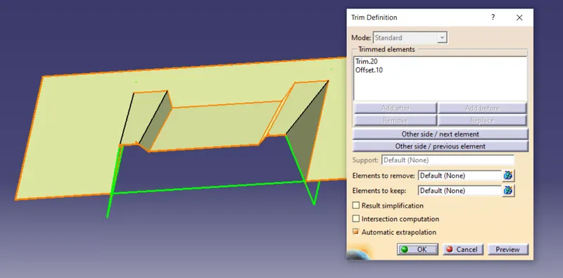
After the extrapolating trim the surface as given in the image. After trimming the surface we gets an shape like the image below. After that offset the surface with the given value. Like the same way the other part is also done.
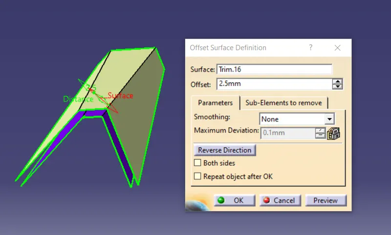
After that select the base part and extract it. After extract follow the same steps made above.
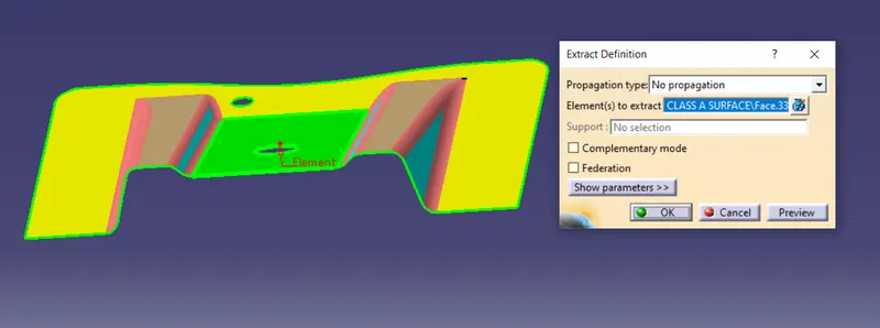
After that trim the offset created before with the base part.
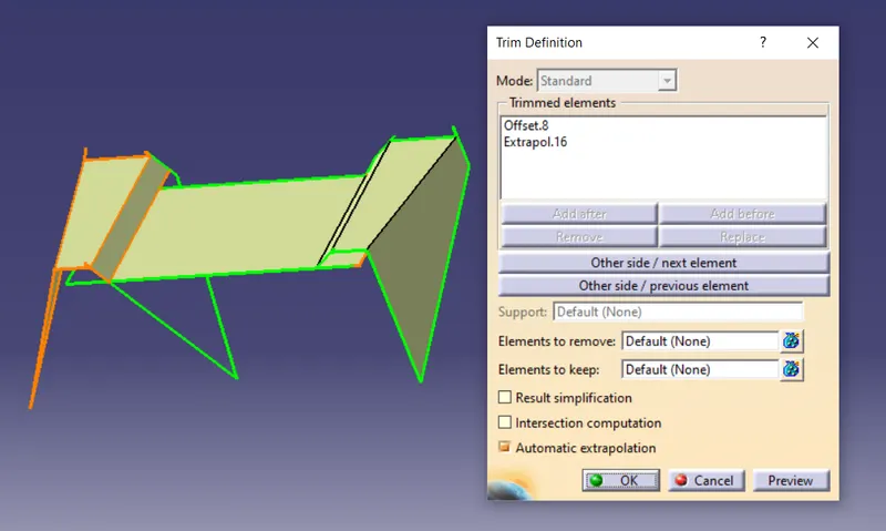
Now extract the bottom surface and follow the steps performed before. After all the process the bottom part is trimmed with the part created before.
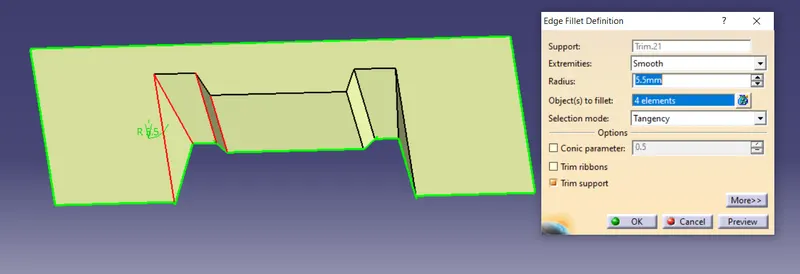
Now the fillet measure the radius in the surface of A or measure it in the intersection line created at the starting stage.
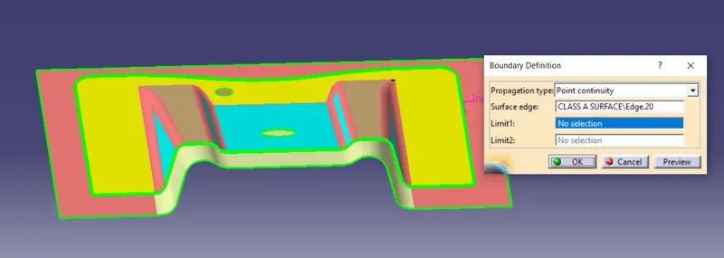
Make sure that the class A surface and class B surface has some distance. After that like the boundary in the class A surface. An boundary is created on the surface.
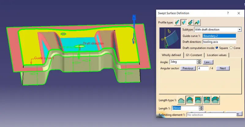
With the swept surface option select the second option i.e., line and changing the subtype to with draft direction now select the boundary and for the draft direction select the tooling axis. The gets and surface lengthened.
After that using the join option to join everything into an single component.
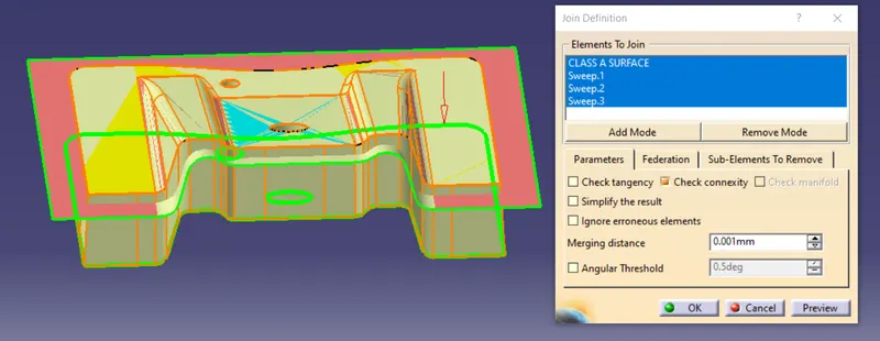
After join the surface is trimmed. After trimming we gets the C class surface which connects the class A and B. After that go to part workbench and convert it into closed surface.
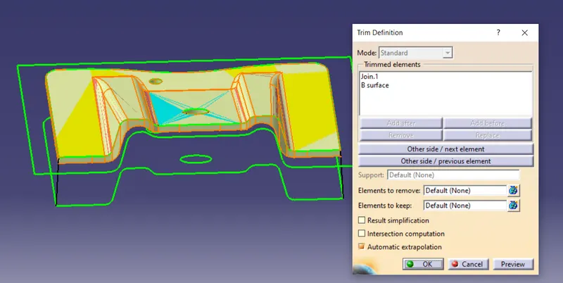
The Final output
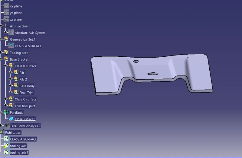
Result:
From the given base bracket plastic component the axis is made and with the axis draft operation is performed and is made ready for the operation. Now to create the surfaces of A,B and C are made with the swept operation.