Base Bracket Design
DRAWING 1:
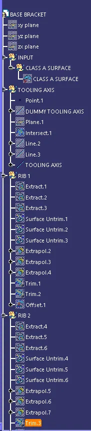
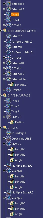
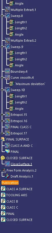
TREE STRUCTURE:
VIEWS:
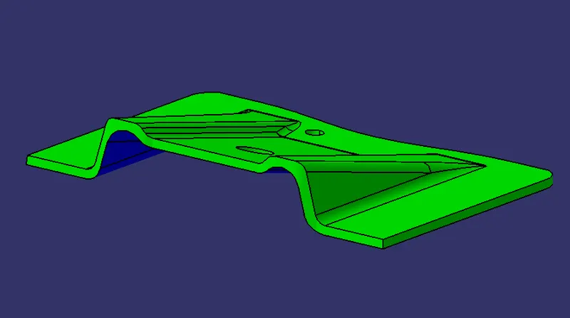
ISOMETRIC VIEW:
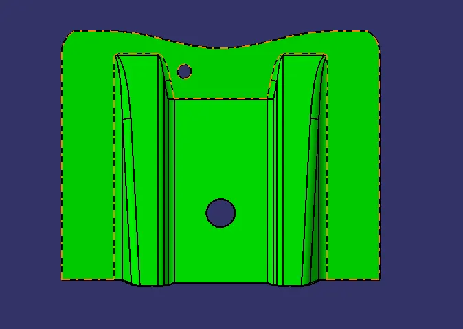
TOP VIEW:
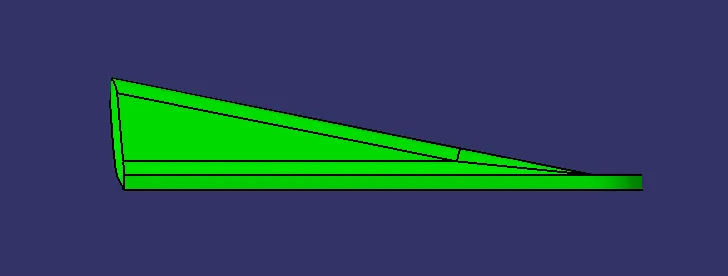
SIDE VIEW:
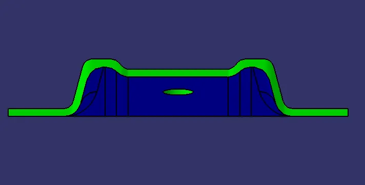
FRONT VIEW:
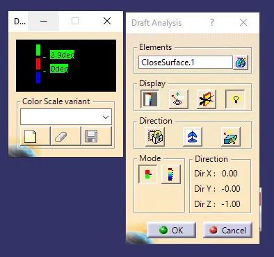
DRAFT ANALYSIS REPORT:
CREATION OF TOOLING AXIS USING BISECTION METHOD:
- In this case, the tooling direction is considered to be Z-direction as it has the easiest ejection and least complications compared to other directions.
- Initially an axis system is created at the centre of the model. a "Dummy Tooling Axis" is created along the Z-direction of the model.
- Then an "intersection" is created using the "Dummy Tooling Axis" as the first element and the class-A surface which is "FAN COVER" (in this case) , as the second element.
- The intersections are created along X-direction as well as Y-direction for the surface.
- For each intersection,the drafted surfaces are extended to create a bisecting line.
- The "Bisectors" of each intersection are again Bisected with each other to generate the "Tooling axis".