3D Finite element Meshing (Tetra Meshing) on Different Components Using HyperMesh Workbench.
Aim: - To perform 3D finite element meshing on given geometry using Hyper Mesh.
Methodology
1) Import the model from its respective location. This model may be the step/IGS /hm file.
2) Perform topology and geometry clean up the geometry, Identify and remove all possible errors in the geometry.
3) Extract Mid-surface from the actual geometry. For 3D meshing, mid surface extraction is not needed as we have to do meshing on the outer surface or directly deploy mesh.
4) Deploy type of 3D mesh depending on the requirement on the geometry as per given Quality criteria.
5) Check for any Quality failure (Ted collapse)and remove them.
Quality Criteria: -
1)Target length for Tetra = 5 mm
2) Elements sizes: Min- 2mm, Max- 7mm
3)Ted collapse = 0.15
There are two types of 3d elements
- Tetra Element Meshing: - The tetra elements have 4 nodes as per the below image.
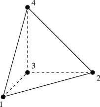
We are using tria mesh here on the outer surface of the part. So basically, on the surface, we do a normal Shell mesh but using Tria elements only. The basic idea is to create a close volume using shell mesh and then fill that volume using tetra elements which are nothing but 3d / solid elements. This method is called a 2d to 3d element conversion. This is one of the three methods that we are gone see in the further segment of the report
For example, take a cube. The Square has 6 sides. So, we do shell mesh on each side/surface of the cube and then fill it's inside with tetra elements.
These tetra elements only follow the surface mesh for the first layer of mesh then it just fills the entire volume without following any pattern that’s why it’s also called Unstructured Mesh. The inside tetra element doesn’t follow the surface mesh pattern through the geometry.
- Hexa element meshing: - For its description we can say that it has 8 nodes as you can see in the image.
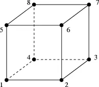
Unlike tetra elements, the Hexa elements follow the mesh pattern through its volume. You can witness the same mesh pattern on either side of the body. (Penta element serve the same role as Hexa the only difference is their shape). The Hexa mesh is called a Structured Mesh.
Only Quad elements are used in Hexa meshing.
Let's take an example of a cube again, But this time we do shell mesh on the surface by using Quad elements and follow that pattern to the other side of the face. We have to do this for each side of the cube. After shell meshing, we just have to patten that mesh so it can fill the inside empty volume.
In the Hyper mesh, a special Deck/panel is available as shown in the bellow image which contains the options related to different types of 3D meshing.

Fig.01
Types of Tetra Element Meshing
1) 2D to 3D element conversion: - As we discuss in the above tetra element intro. We first have to deploy a 2D element mesh on the Surface of the geometry. and then creat the tetra mesh with reference to that 2D tria mesh.
In this Assignment, I get A “Housing” Assembly contains two parts, lets explore the method through the live example itself,
For showing the first method, I had to take only the hub part.
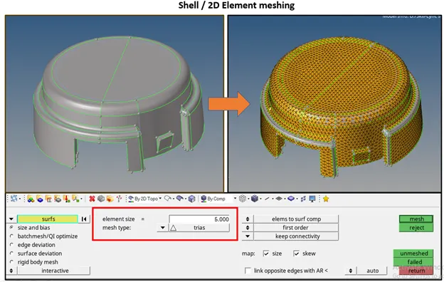
Fig.02
As you can see in the above image, I had deployed 2d mesh over the geometry using 2D Mesh Deck. I Had used the “automesh” option from the deck. The Panel you are seeing in the above image is the Subpanel from the auto mesh option which will give you the freedom to set the element target length as well as the Type of the mesh.
The Target length of 6 mm is given by the respective authorities.
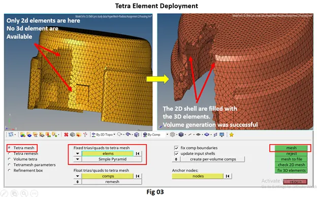
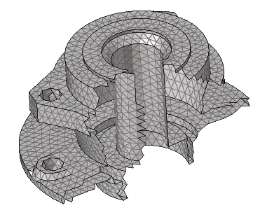
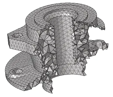
Here you can see the transformation from the 2D element to the 3D element.
2)Volume Tetra Method: - Unlike the previous method we don’t have to deploy a 2D shell element on the geometry in this method. The o7ption “Volume tetra ” will do direct volume meshing on the given component. Time taken by this method is also significantly less than the 2d-3d conversion method.
Volume Tera is the part of 3d mesh deck and you can find this option in 3d panel inside the “Tetramesh”
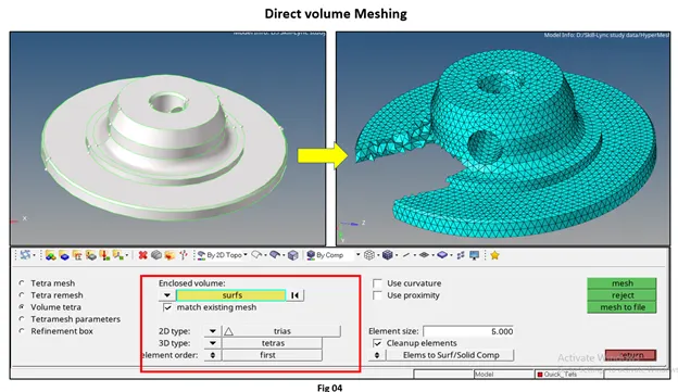
As you can see in the above image, we get the option for the selection of both types of mesh. (a mark by the red box) as well as Element size in a single panel only. After putting appropriate values and press the “Mesh” Button from the panel, Hyper mesh automatically deploy mesh on the model.
I had selected the model and feed the data given to me to generate the result we are seeing on fig 04.
3) Utility Browser Method:-
This method is easy and effective among all three methods. The main reason is under this method the Hyper mesh automatically does a defeaturing and meshing in one scope. Due to this feature, this method is praised by engineers.
To do meshing with this method first I had created a new PID and moved (tool à Organize) all the 3D elements into that newly created PID. Now, my geometry is free from the mesh and I can perform this method on the same geometry.
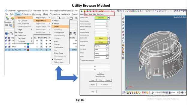
You can access the “Utility Browser” from the menu bar as suggested in the above image. The Utility Browser contains the same options like the type of mesh, target element size. We only have to select the component from the graphics window to deploy the mesh we want.
I had performed the tetra meshing using the Utility browser as the result is as follows,
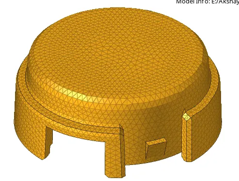
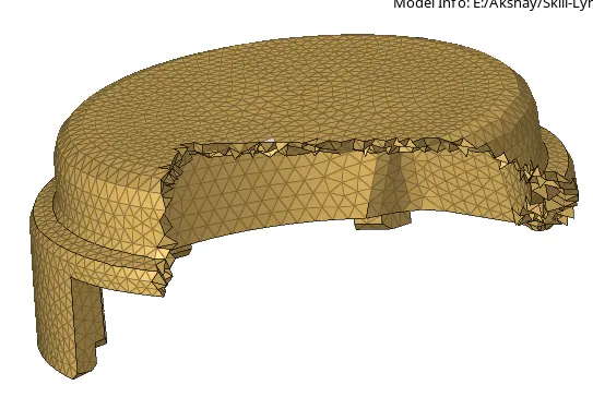
Out of these three methods, the first one which includes 2D element meshing over the surface and then converts it into the tetra (3D mesh) with reference to the deployed 2D element is mostly used by the Industry. The reason is 3D meshing is needed precision., With the other two methods, the Tool only deployed rough tetra mesh over the Geometry which is acceptable in some cases but in the majority of the cases, it's not a good practice.
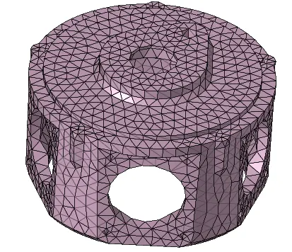
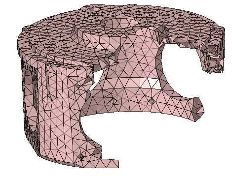
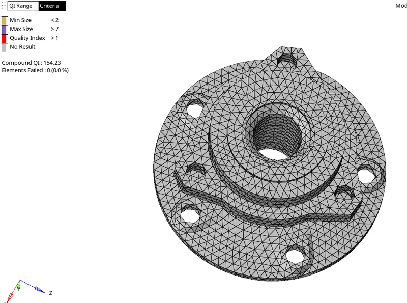
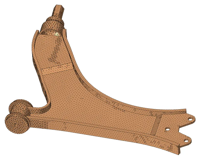
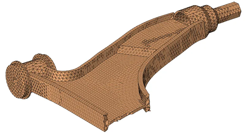
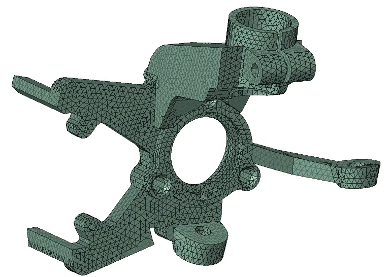
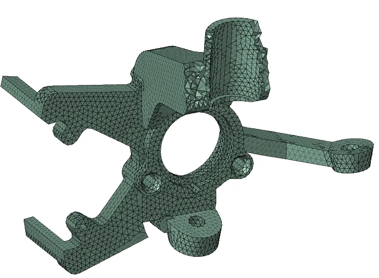
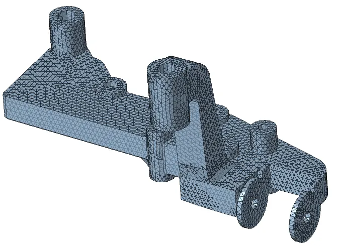
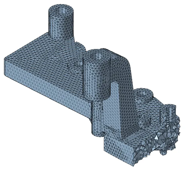
So for the other two components, I had followed the First "2D to 3D element conversion" method. the models are as follows
Errors during Meshing
During 3D element meshing the engineer more focus on the Ted collapse Quality criteria. Ted collapse is only applicable to the tetra elements.
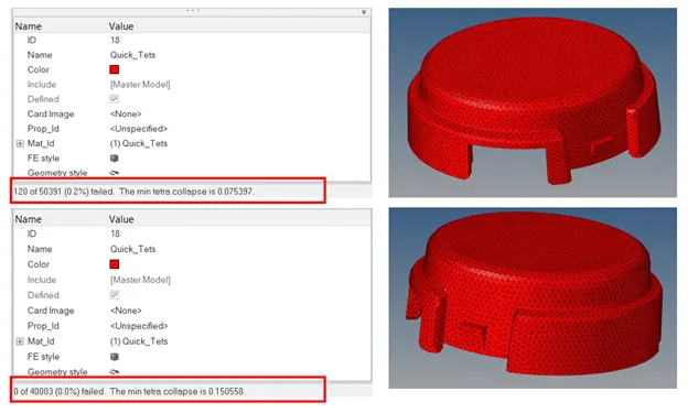
In the first window, you can see the ted collapse is 0.2% and 120 elements are failing for it. I had faced this issue during mesh deployment using the Utility browser. I solved this quality by using “Tetra remesh” under the tetra mesh panel.
3D panel --> Tetramesh --> tetraremesh
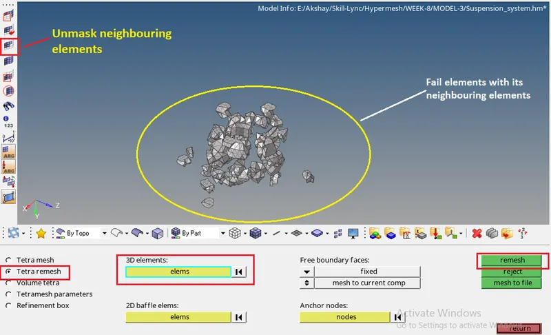
First, we have to mask the fail elements from the all-good elements using the Mask option, then Unmask neighboring elements. After calling out the neighboring elements we will get the elements as you see in the above image.
The next step is to select the elements and hit the remesh, it will do remesh and repair the elements which are failing for Ted collapse. If there is still some fail element that we have to clear it out using the manual "translation" option.
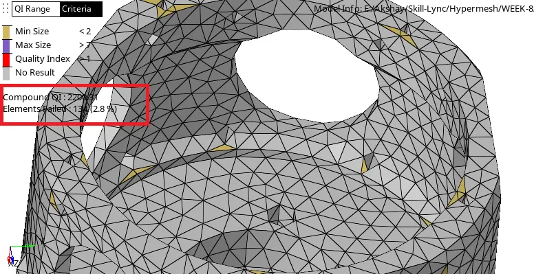
As you can see in the image the 2D elements are failing for the Min Length and we are excluding them because Geometry cathing is the main thing here. If we tried to eliminate this Quality failure, it would cost us a very bad feature capturing.
I have face this issue while doing meshing over the other components also I have tried to Minimize the error by using an elemental clean-up option but in some cases, I have to give up on fail elements to capture the Feature or geometry.
Conclusion
1) 3D meshing/volume meshing / Solid meshing is only done on the part which has a thickness of more than 5mm. Mainly used for Casting/Forming Component.
2) In the Utility browser method, the defeaturing is done on the model Automatically along with the 3D mesh Deployment. It's a Fast process but the Defeaturing done by this method is not that good if e compare to the Manual Defeaturing, Some time it excludes important Features.
3) Min Length and Max. Length criteria wouldn’t get applicable to the solid mesh as the elements are 3D elements in nature and we can’t distribute them on basis of 2d perimeters. Though we did check Tet collapse for 3d elements.
4) Volume Mesh option is good for Deploy 3D mesh over the solid body as well as surfaces.
5) 2D to 3D element conversion is the best method because it will give us freedom over the defeaturing, and deploying mesh surface by surface will help to reduce the Min and Max length quality failure in 2D Tria elements. So the end result will be good Tetra mesh with Min Ted Collapse.