Tetrameshing in Hypermesh
Objective:
The objective of this project is to generate the 3D tetra mesh of the given components based on the quality criteria and understand the different ways to generate 3D tetra mesh in Hypermesh.
Procedure:
Tetrahedral is a four-nodded solid element which can be generated through the tria element by creating a volume and also through the existing volume of the geometry. These elements are used where the geometry has high thickness and complexity. The image below is a representation of a Tetra element. Tetra element will have 4 triangular faces with four nodes joining them together.
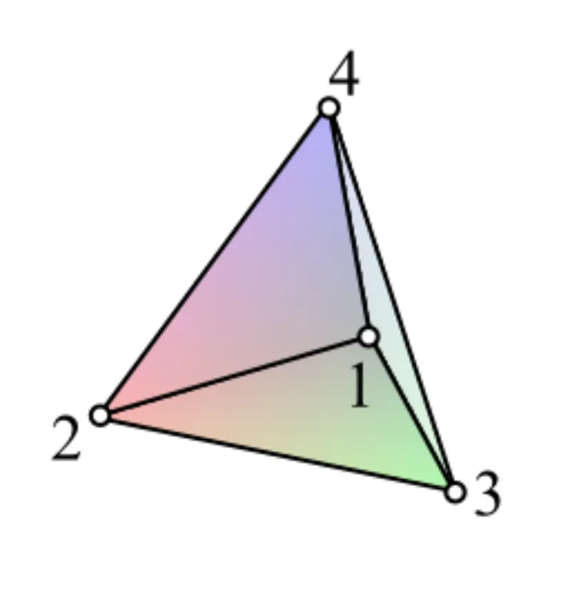
There are three methods to generate Tetra Meshing in Hypermesh as stated below:
- Standard tetra meshing (Conversion of 2D tria to Tetrahedral Elements, by using Tetra Mesh panel).
- Quick tetra mesh (Using the Quick Tetra Mesh, from the Utility panel).
- Volume tetra meshing (Using the Volume Tetra Mesh panel).
Now, let's see the process of generating a tetra mesh using these methods.
Model 1:
First given model is a hub and the housing, shown in the image below.
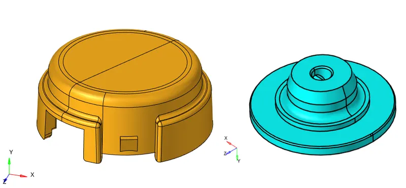
These two components are meshed using the first method, i.e., converting 2D tria to 3D tetra. For this model, the target element size is given as 5mm. Minimum and maximum size is 2mm & 7mm, respectively. And, tet collapse value is 0.15.
First, the model geometry is imported into the Hypermesh. As we are going to mesh the surfaces first with 2D elements and then converting them to 3D, we don't require any solids in the model. So, the next step is to delete all the solids. In this model, the hub component contains solid, which is deleted using the delete>solid tool.
The next step before meshing is to properly understand the geometry and fix any error in the geometry. After that cleanup is done, keeping in mind the quality criteria. Any feature/region where elements might fail for minimum length is defeatured or surface edge toggled.
Now, 2D meshing for both components is done using the 2D>automesh>QI optimize tool, keeping the element size as 5mm, and trias as the mesh type. Using the edit criteria option, minimum length and maximum length is set to 2mm & 7mm, respectively. The image below shows the 2D mesh generated.
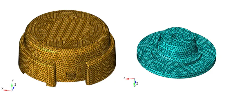
Now, elements are checked for minimum and maximum length criteria and cleared if failing. No elements were found failing.
The next step is to generate the tetra mesh by going to 3D>tetramesh>Fixed trias/quads to tetramesh tool and selecting all the elements of one component. Under Tetramesh parameters, tet collapse value is set to 0.15.
Once the tetra mesh is completed, all the elements are checked for tet collapse. No element was found to be failing. In case some elements had found to be failing, they can be isolated and repaired using the translate node tool or remeshed.
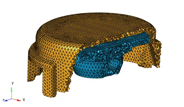
The image below shows the tetra mesh with few elements masked.
Model 2:
Tetra mesh for the model shown below is generated using the Quick tetra mesh tool, with an element size of 6mm.
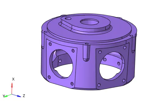
Quick tetra mesh also works similarly to the above method. It first generates 2D surface elements and then converts them to generate the tetra mesh but is a much faster and automatic method to generate tetra mesh. The drawback of this method is that the user has no control over the mesh quality.
The initial process before tetra meshing is the same, i.e., import the geometry, delete solids, & cleanup for errors in geometry. There were some free edges in the model which were repaired using the toggle edge tool.
Quick tetra mesh tool is accessed by going to View>Browsers>Hypermesh>Utility>Geom/Mesh>Quick tetramesh. In the Quick tetra mesh tool, the component & surfaces are selected, mesh size is set to 6mm, and mesh type is set to Trias only. After clicking on mesh, a new component is generated with the tetra mesh.
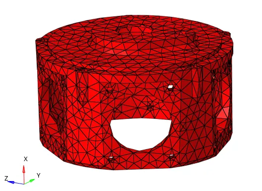
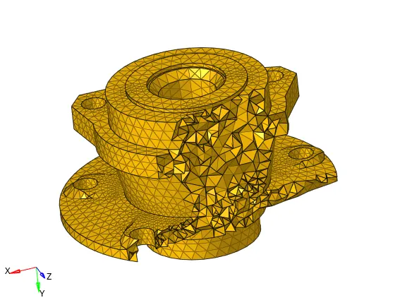
It can be seen that the mesh generated is not of good quality. Therefore, this method is only used when quick meshing is required and mesh quality is not a concern.
Model 3:
The third model is shown below, which is a part of the suspension assembly and consists of four individual components.
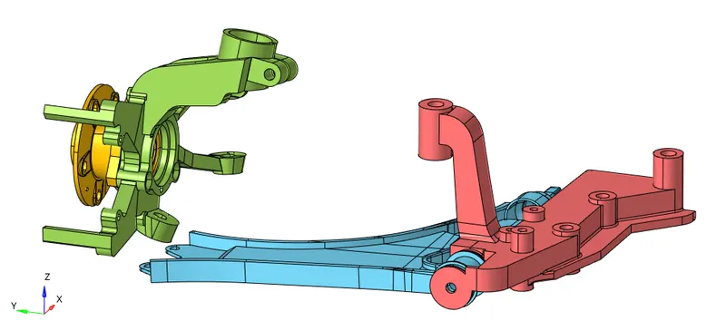
These components are meshed using the volume tetra meshing method. This method also provides a quick way to generate the tetra mesh for solid components and has some specialized tools to control the mesh quality like proximity which creates smaller elements next to small features to make a smooth transition from small to large, and curvature which will place more elements along curved surfaces.
The initial process is again the same, i.e, import the geometry, check the model, cleanup, and defeature the components.
Tetramesh is then generated for each component one by one. To generate the tetra mesh, the Volume tetra tool is selected under the 3D>tetramesh tool panel. The element size is set to 6mm. Use curvature and use proximity option is checked and the minimum element size is set to 2mm. Under Tetramesh parameters, fill voids, fix midnodes, and smoothing options are checked.
Mesh generated for each component is shown below.
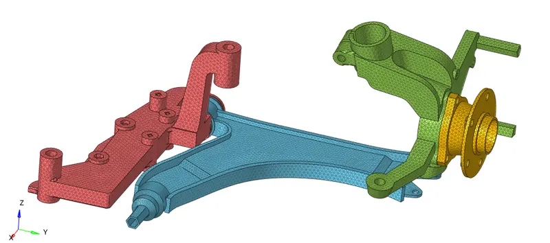
We can see the tetra mesh generated by masking a few elements as shown below.
Conclusion:
All the given components were meshed successfully according to the quality parameters using three different methods.
Note: Please find the .hm files for all three models attached.