Week 8 - Challenge 1 - Draft Analysis on a Fan Cover
AIM
To create the tooling axis for the given Fan cover model meeting the requirements of the draft angle and perform the Draft analysis on the model.
INTRODUCTION
Draft Analysis,
The Draft Analysis command enables you to detect if the part you drafted will be easily removed. This type of analysis is performed based on color ranges identifying zones on the analyzed element where the deviation from the draft direction at any point, corresponds to specified values.
Draft angle
Draft angles are the degree of taper that is incorporated into the side wall and cores of the die cast tool to aid in the removal of a part. Primarily, they function to reduce the friction between the part and the tool as it is ejected. Without draft angles, parts can be stripped, dented, or get stuck in the tool.
EXPLANATION
Here we obtain a draft analysis and tooling axis creation for given Class A Surface of fan cover design,
This the The given Model of Class A Surface Fan Cover
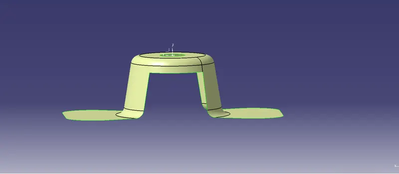 .
.
First we determine the given object and create a new geometrical set in the name of tooling axis, to check the boundaries are closed in the Class A surface model by using boundary feature.
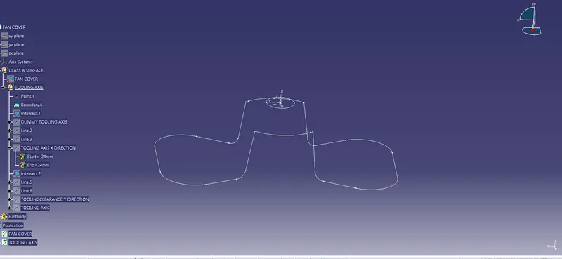
To create a intersect line in the fan cover model by using intersect feature in plane of ZX plane and create a dummy tooling axis in the model .
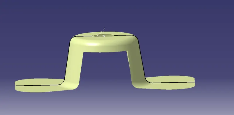
Form two cross lines in the intersected boundaries or create a Tooling Clearance X Direction line using bisecting line in the X Direction.
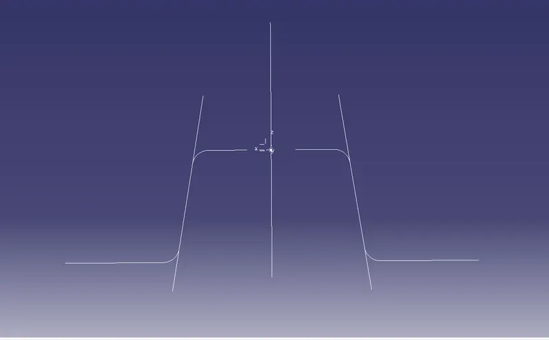
The line in blue color is bisecting line which creating the X direction
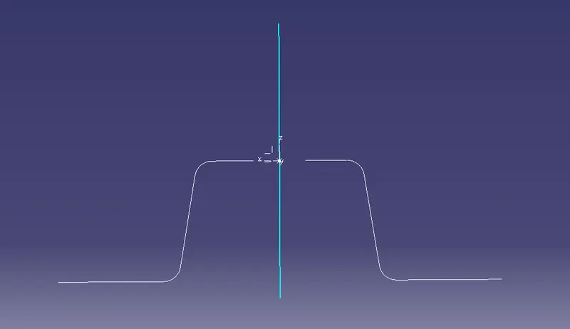
As same process to create the another tooling clearance line for Y Direction in plane YZ plane.
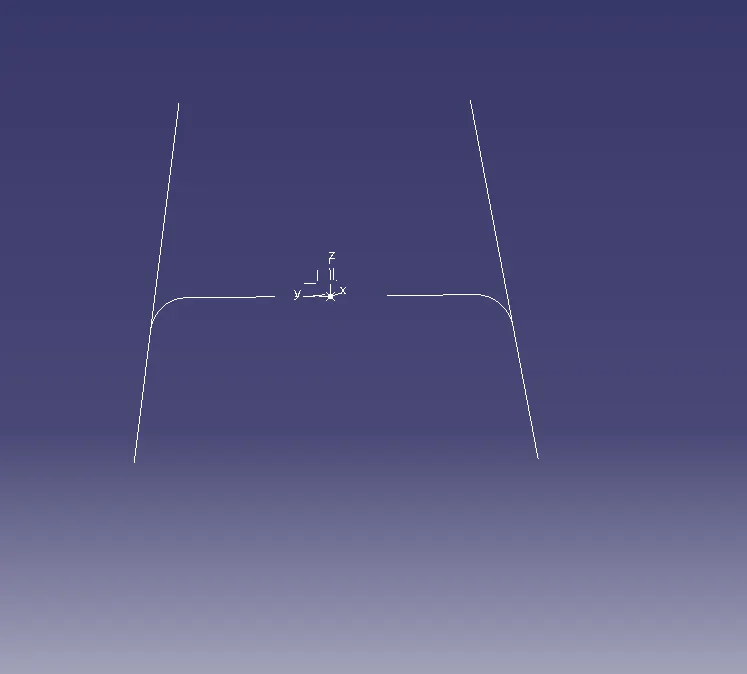
The line in green color is bisecting line which creating the Y direction
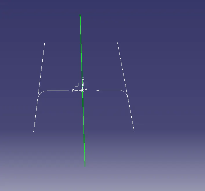
The line which Tooling Axis wiht help of bisecting line of X and Y direction.
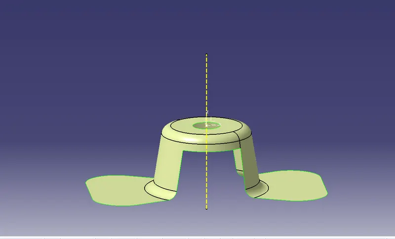
After forming Tooling axis publish the fan cover and tooling acis line for draft analysis.
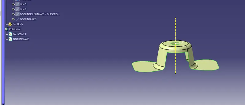
Before enter the draftt analysis have to check model is in material in customize view parameters.And then open Draft analysis fix the direction along with Toolling axis using in the direction and lock it.
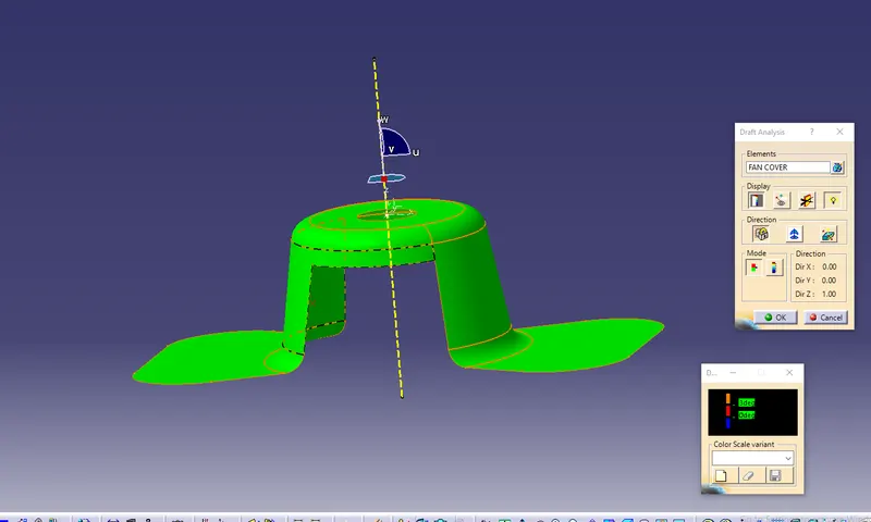
Check the model is positive in angle by drage and select the surface in the model and its changed to green color. Thats we analyse the surface in positive angle and analyse angle in the each surafce of the model using running point option.
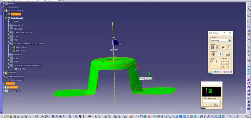
Finally we analyse the draft angle in the given Calss A Surface Model and shown in the above pic as angle is positive which are in green color.
Isometric and Orthograpic view of FAn Cover
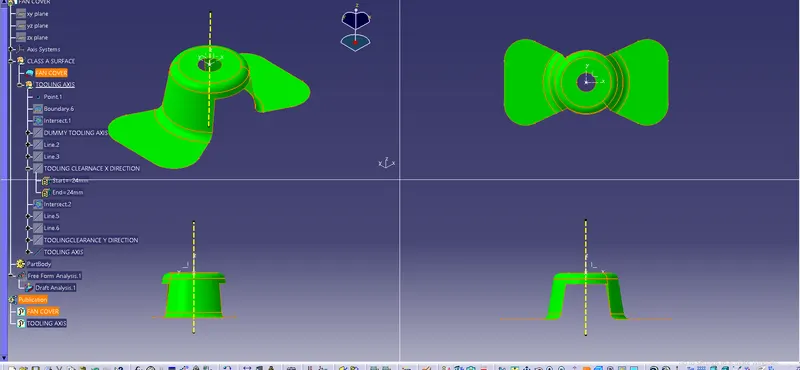
CONCLUSION.
Here we analysed the draft angle with help of created Tooling axis in the given Class A Surface od Fan Cover Model.