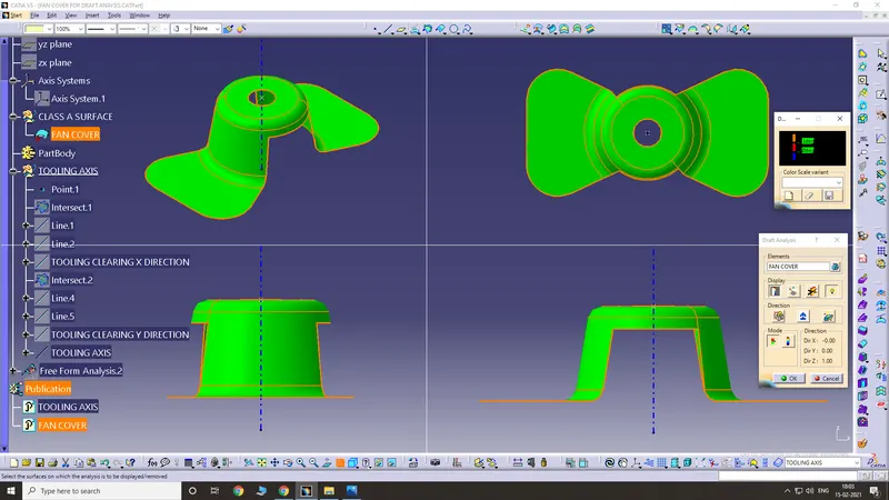
Week 8 - Challenge 1 - Draft Analysis on a Fan Cover
Here is the default CATpart given in the question.
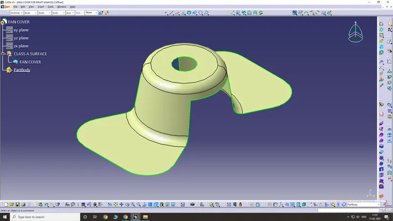
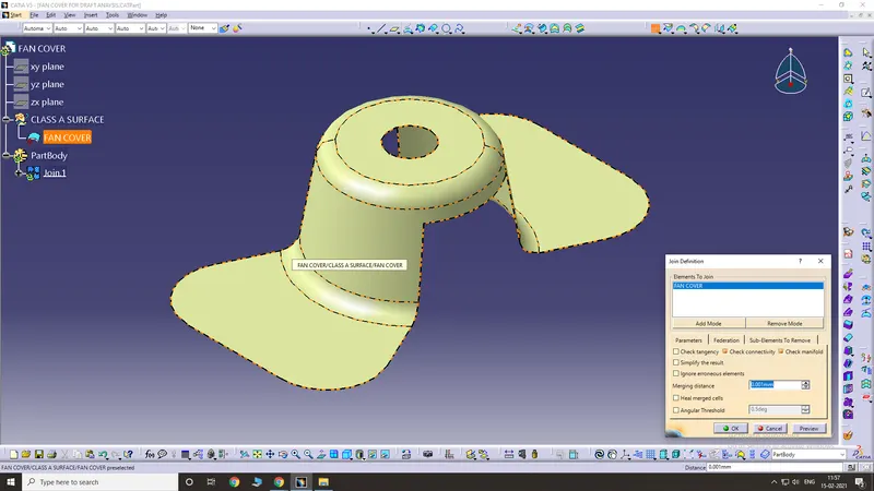
First of all, ensure that there are no gaps between surfaces (check continuity of class A surface). For that, use join command and check for continuities.
Next, find the tooling axis of the component (Tooling axis is the direction in which the mould opens or the core and cavity opens).
For determining the tooling axis, we have to intersect the component in X and Y planes and create individual axes. Finally, create a bisection of both the X and Y axes to form the final tooling axis.
Tooling axis in X direction
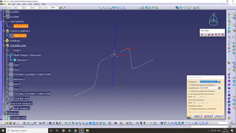
Create lines on both ends and extend them. Now we have to create a bisection between these 2 lines. This is the tooling axis in X direction
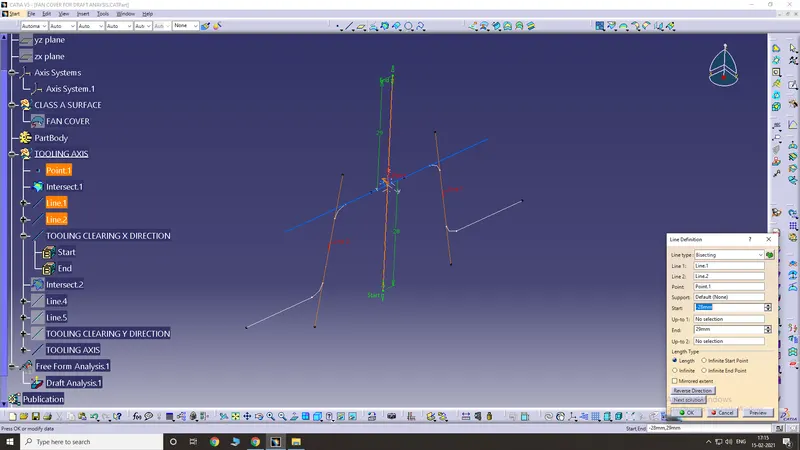
Similarly, create the tooling axis in Y direction
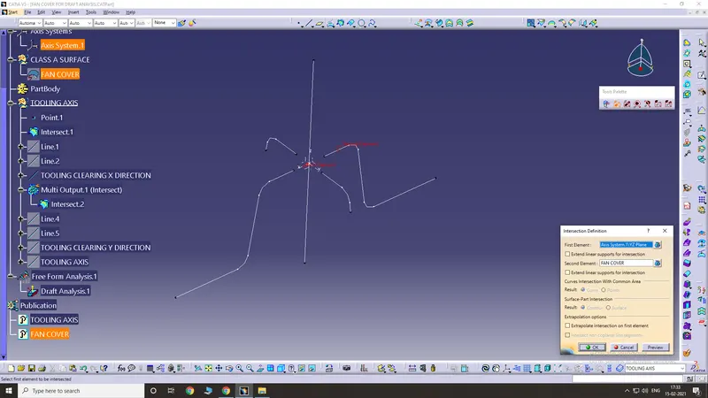
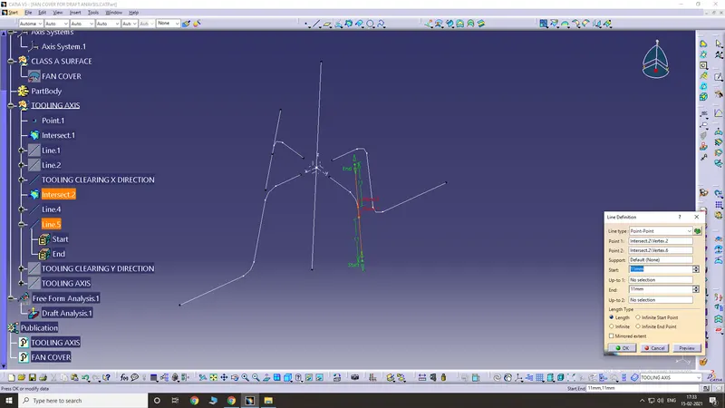
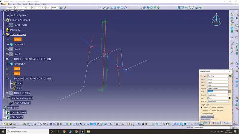
Now for the final tooling axis, bisect both the above-created axes.
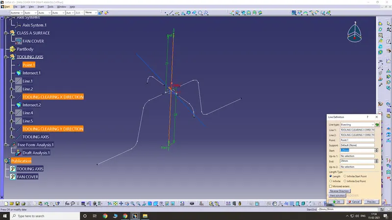
Final tooling axis (coloured in blue)
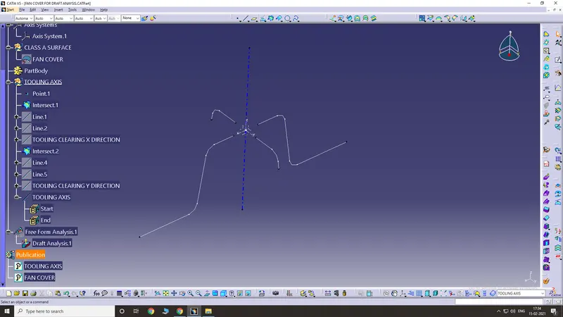
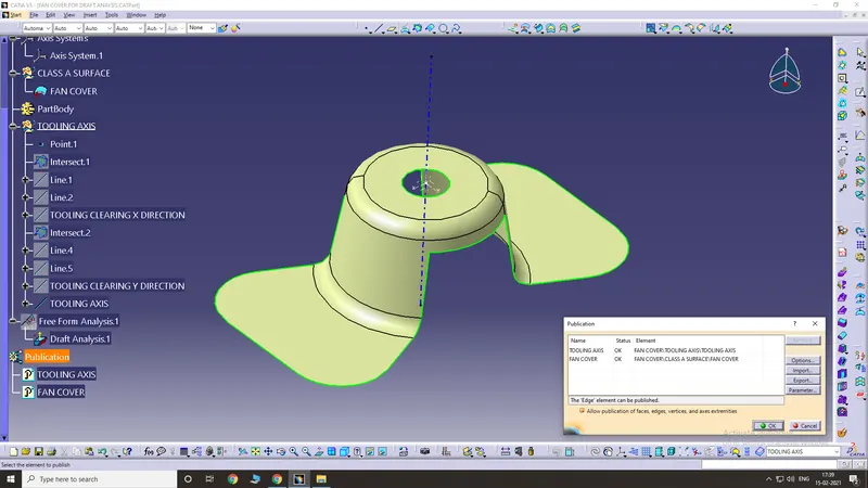
Next step is publishing. select tooling axis and class A surface and click OK. Publishing is done for better visibility.
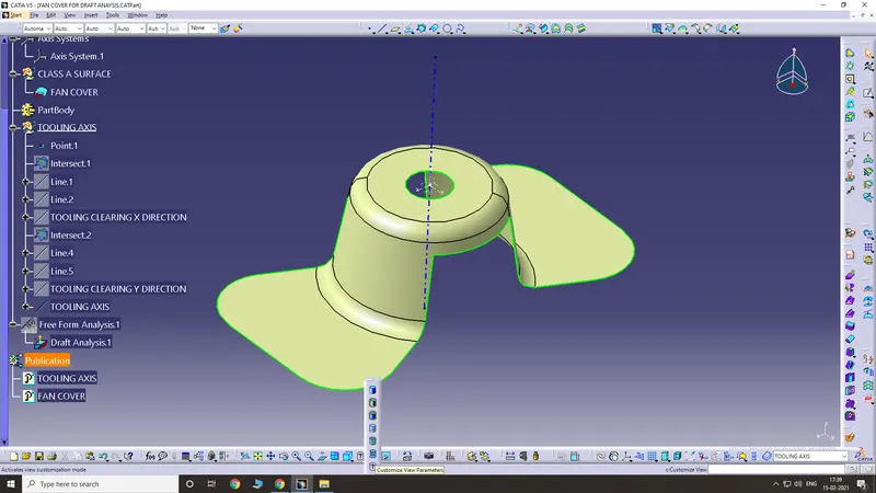
Next, ensure that "material" is ticked in "customise view parameters" tool.
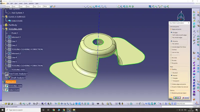
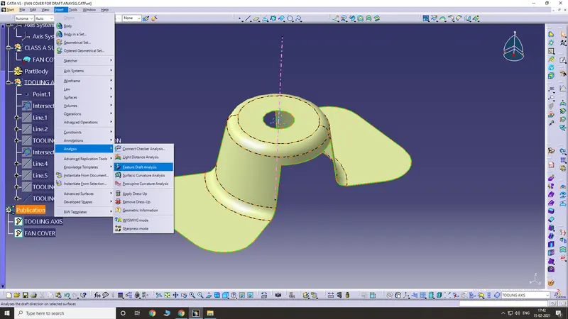
Next up is draft analysis. For that go to Insert -> Analysis -> Feature Draft Analysis
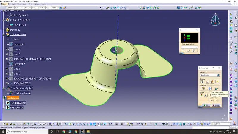
Use the compass tool and place the compass along the tooling axis line.
Zoom out the screen to find the compass.
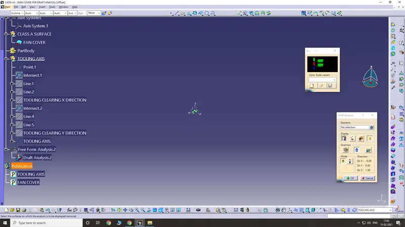
Place it along the tooling axis
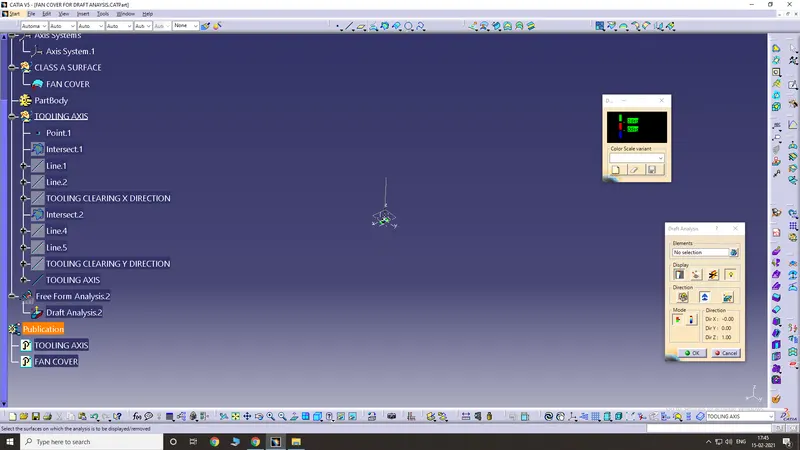
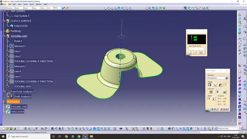
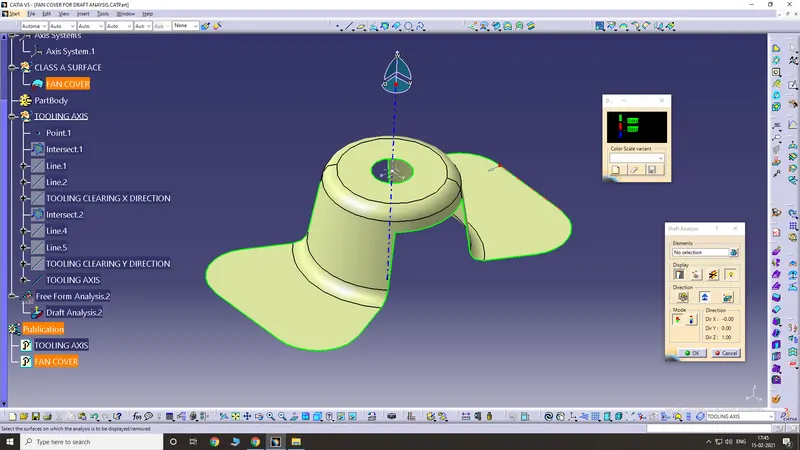
Use the lock tool next and when you see a point showing, place that point on the class A surface and click on it. The class A surface will turn green.
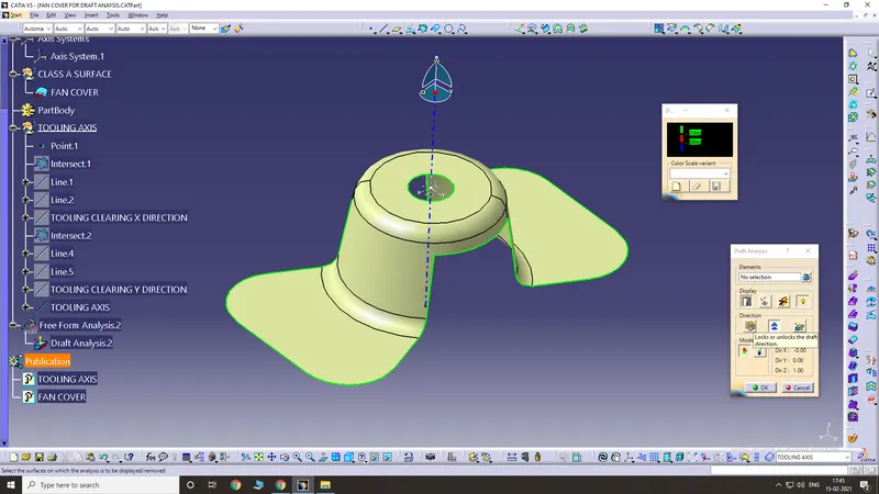
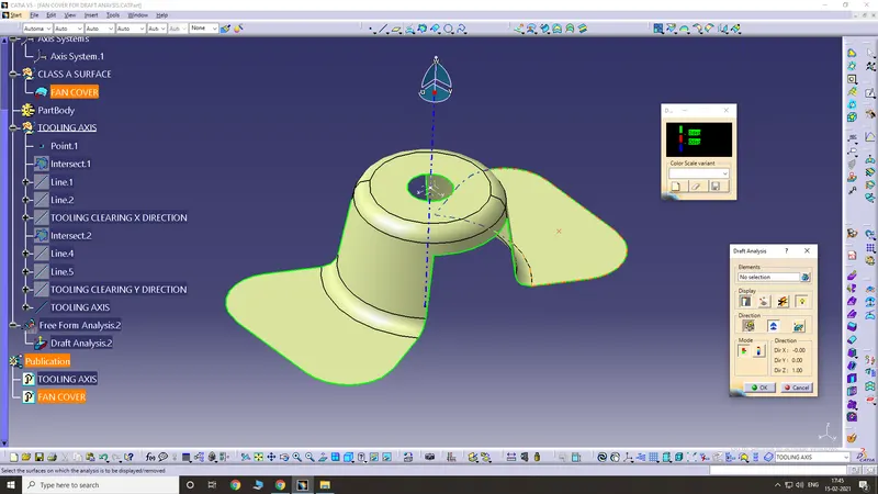
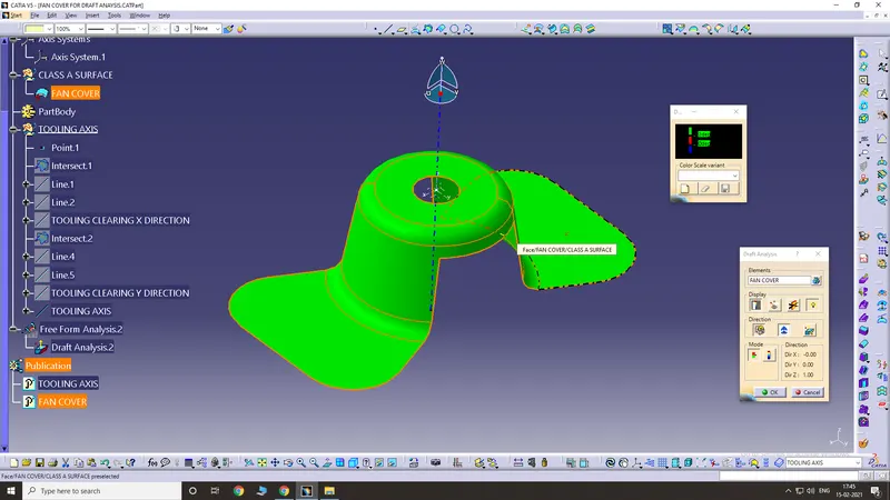
Change the draft angle to 3, since we know that the minimum draft angle is 3 degrees.
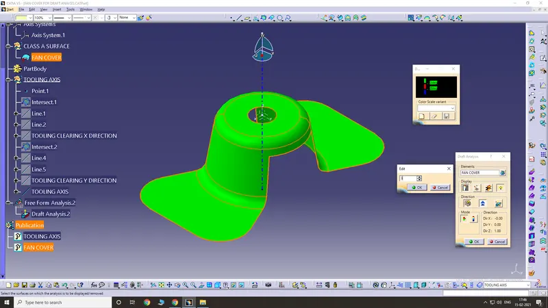
Now we have the draft analysis and the component is ready to design.
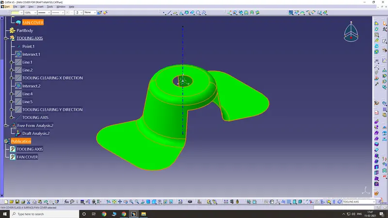
Final product