Week 8 - Challenge 1 - Draft Analysis on a Fan Cover
OBJECTIVE:
To perform draft Analysis on a Fan Cover.
PROCEDURE:
Draft Analysis:
Draft Analysis is performed on the fan cover to check whether the design is feasible for production. With this Analysis, we are able to check the draft angle of the part which helps to remove the part easily in the production process.
Tooling Axis:
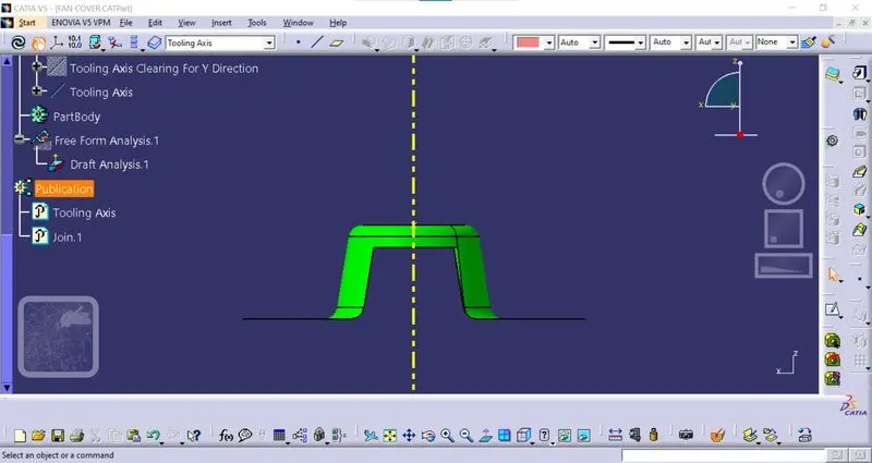
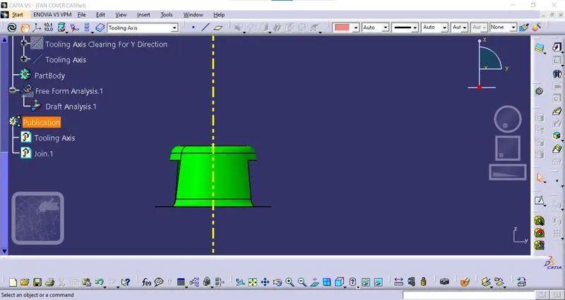
The tooling axis is created in the direction in which the core and cavity open. For this, we can analyse it visually, and create a suitable tooling axis of the part. So the tooling axis which we created in Z-Direction is clearing the centre hole of the fan cover.
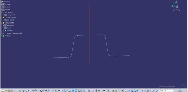
The bisecting method is used for finding the real tool axis :
- For this, we have to insert an axis system and take intersections through the ZX Plane with Class-A Surface and we will get two curves. And name it as a dummy tooling axis.
- We have to check if the surface which is parallel to the tooling axis is not creating any problems with the tooling axis which is in (90 degrees).
- For this, We have to make a point to point surface lines to check the intersection of the surface lines with the tooling axis.
- After this, we have to bisect the two surface lines and select the bisecting line in the vertical direction. This axis will be our tooling axis of X-Direction.
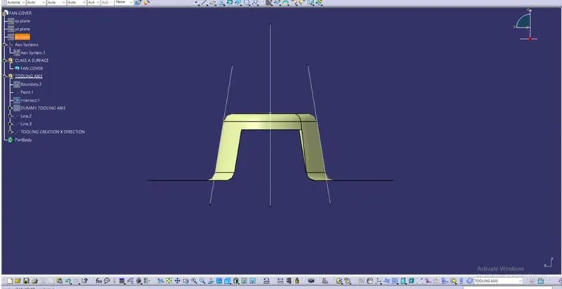
- Similarly, We will follow the same procedure for the Y-Direction tooling axis by intersecting the YZ PLane of the axis system.
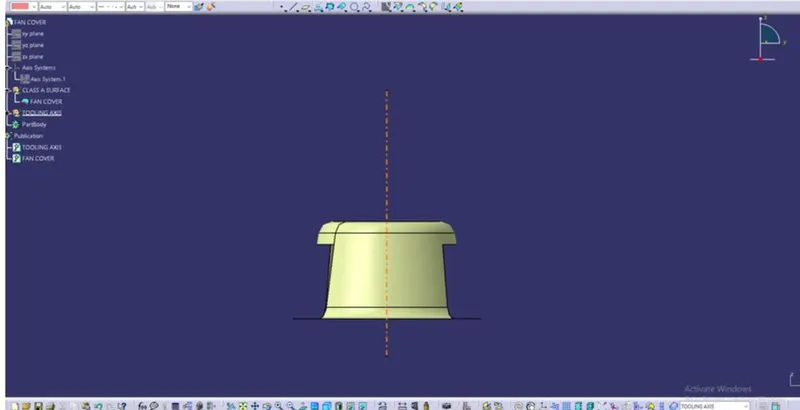
- To Get the Final Tooling Axis we will bisect the Tooling axis of the X-Direction and the Y-Direction.
Publication:
- The Tooling Axis and the Class A surface is published using the Publication option in the Tools Menu.
- With this, we can easily Hide/show our components.
Performing the Draft Analysis
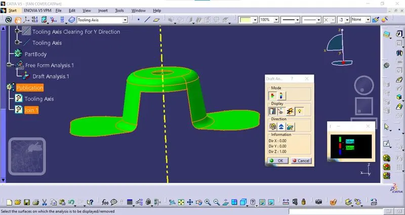
- The initial step is to customise the view mode to material
- Go to Insert < Analysis < Feature Draft Analysis.
- Clicking on compass<Display<Draft Analysis window.
- Align the compass with the Tooling Axis.
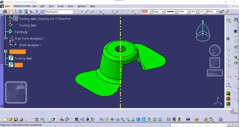
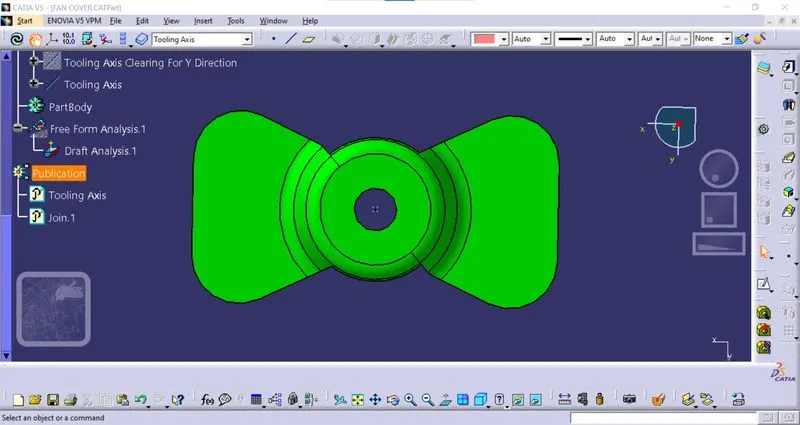
- The Draft angle of 3 degrees is generally required which shows a green colour surface.
- Analysis under the running point shows the draft angle in degrees.
Observation:
- The areas in Green colour will clear the Tooling axis with the required draft, making the part manufacturable.