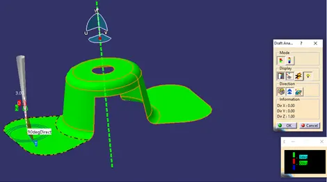
Week 8 - Challenge 1 - Draft Analysis on a Fan Cover
Draft Analysis on a Fan Cover:
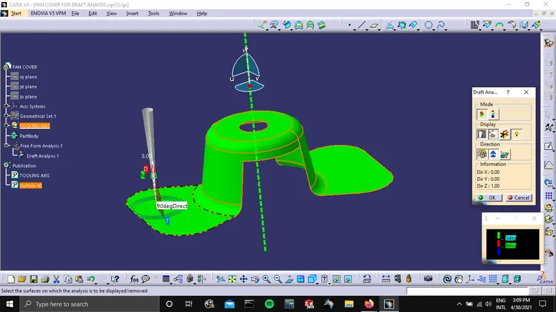
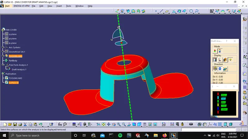
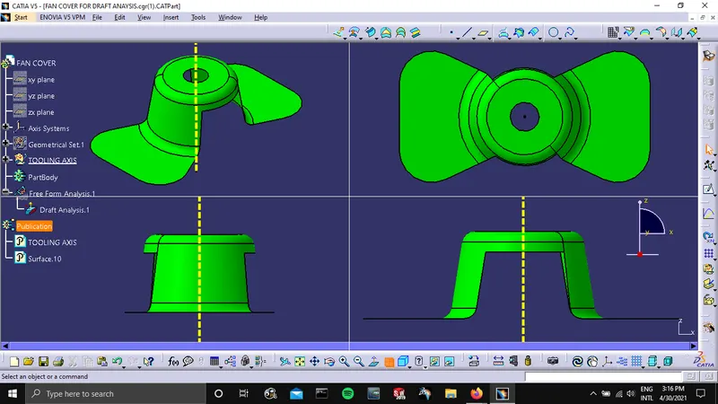
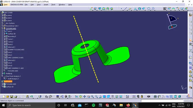
DRAFT ANALYSIS
Draft Angle: The draft angle is the amount of taper for molded or cast parts perpendicular to the parting line. It can be measured in degrees or mm/mm (in/in). As plastic cools, it shrinks and therefore shrinks onto molding surfaces. Because of this and a few other reasons, we draft (angle) the walls of the plastic part, so as the part is removed it breaks free from the molding surfaces easier and without dragging. A functional part for injection molding has to have drafts facing both cavity and core sides to reduce the risk of damage to the parts and ensure ejection. What’s also important is to overcome the vacuum forces by letting air in between the metal and the plastic for the part to release properly. Adding an adequate draft angle ensures that warpage upon ejection is prevented while maintaining a decent cosmetic finish.
- Draft angles are generally a requirement of injection molding design (though there are a select few soft materials, like nylon, that can get away with draft angles of zero).
- Draft should be a part of design for manufacture, and Plastic Product Designer should be aware of its need at the outset of the design process. This allows considerations for design requirements to be taken into account.
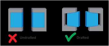
FIG: Drafted and Non-Drafted product.
Nominal Values for Draft angle:
- 3 Degrees is nominal Draft.
- 5 Degrees can also be manufactured. But it will increase the manufacturing cost.
- 7 Degrees for textured surface.
Importance of DRAFT in Injection Molding:
- Reduces the chance of damage to the part due to friction during release
- Reduces wear and tear and chances of damage to the mold
- Ensures a uniform, smooth, unscratched finish when required
- Ensures the integrity and uniformity of other surface finishes and textures
- Reduces overall cooling time by lessening or eliminating the need for unconventional ejection setups
- Most, if not all, of these benefits offer either direct or indirect overall production cost reductions
CREATION OF TOOLING AXIS:
It is the first step involved in performing draft Analysis. Some prerequisites should be performed before creating tooling axis. Check the connexity and inspect surfaces of the class-A surface. Check weather all the surfaces are closed or not using boundary option. Once inspection is complete create separate Geometrical set for tooling axis. Chose axis which clears all the sections, pockets and holes of the surfaces.
For example, in terms of Draft Analysis of a Fan, once visual inspection is complete, we concluded that Z-axis can create all the holes and edges of the class-A surface. As shown in a picture below we can take reference point to crate line called Dummy tooling axis.
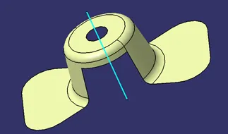
FIG: DUMMY TOOLING AXIS.
Next step is creating clearing axis for remaining two axes. For this create axis system and make sure is not current with reference to point on dummy axis. Once axis system is formed select plane with respect to surface. Use intersect tool to create profile. As you can see in fig. below, we need to check highlighted areas for clearing. Add lines using highlighted point and use those lines to create bisecting line. Rename that bisecting as Axis clearing X-axis. Perform similar operation in remaining plane.
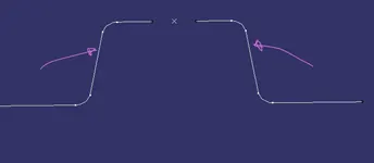
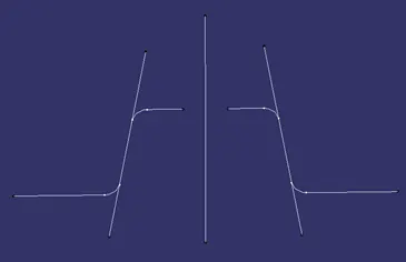
FIG: CLEARING AXIS
Once all clearing axes are formed use bisecting line feature to create tooling Axis. Change the graphics of tooling axis and published it. After tooling axis is published performed Draft analysis by following steps below:
DRAFT ANALYSIS:
- Check weather class-A surface is in material mode. (Customized view – shading – material).
- Add draft analysis toolbar. (Insert- Analysis- Feature draft analysis).
- By clicking on the compass direction icon within the draft analysis dialogue box. This will snap the compass onto the part’s origin. Figure below shows the steps involved with moving the compass.
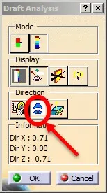
- Now that the draft direction is fixed, you can gather the draft angles along different surfaces using the “on the fly” mode. Simply activate the icon within the draft analysis dialogue box and hover your mouse over the surface in question.