Week 8 - Challenge 1 - Base Bracket Design
Challenge 1 - Base Bracket Design
Requirement :-
Create the Base Bracket Plastic component through the given Class-A surface. To begin with, the tooling axis for the given Class-A Surface should be created meeting the requirements of the draft angle and at the end perform the Draft analysis on the model.
Thickness of Plastic Part - 2.5 mm
NOTE:
- Tree Structure
- Ensure Proper Tree Structure
- Geometrical sets should have a proper name based on the sketches present inside of it
- All the sketches should be created under the Geometrical set
- Use the Close Surface feature to make a solid body from the surface.
- Publications: Use the publication option and publish the below
- Tooling Axis
- Class A, B, and C surface
- Report
- A detailed report should be done explaining the draft analysis and the tooling axis creation.
- An explanation should be given on the way of creating the tooling axis, particularly the Bisecting method.
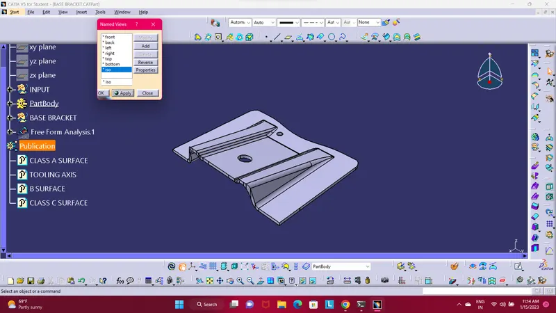
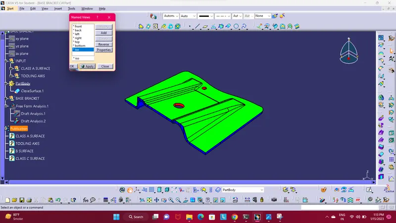
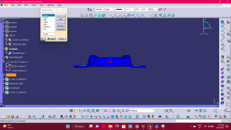
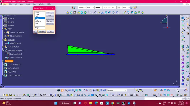
Below are the follwing image / screeen shot of 3d plastic model part in a varios orientations.
- ISOMETRIC VIEW.
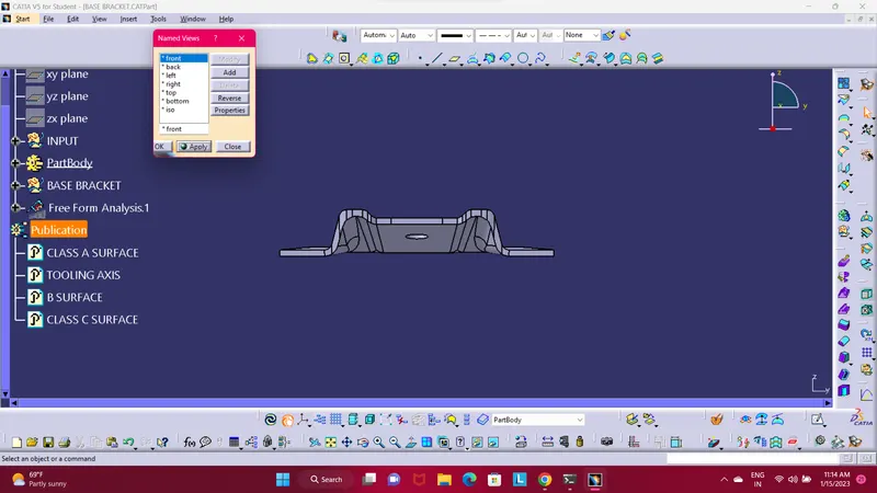
- FORNT VIEW.
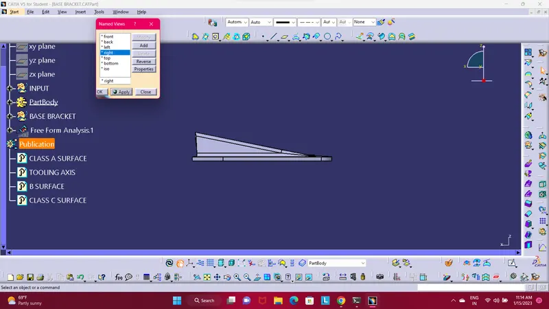
- SIDE VIEW.
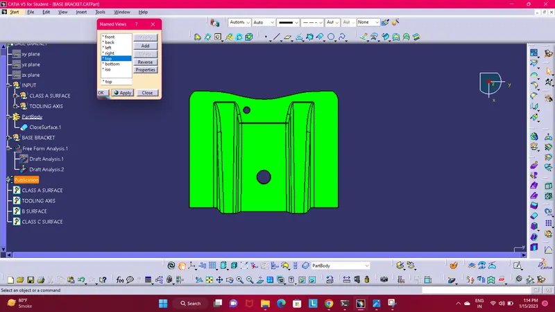
- TOP VIEW.
- A detailed report should be done explaining the draft analysis and the tooling axis creation.
First with the help of given class-A surface create a tooling axis.
To create a tooling axis first defined a perfect tooling direction such as (x-direction, y-diretion and z-direction) choose z-direction which more sutable or visible.
Z-direction means top view. Then make a dummy tooling axis through the hole in the model as shown in below image.
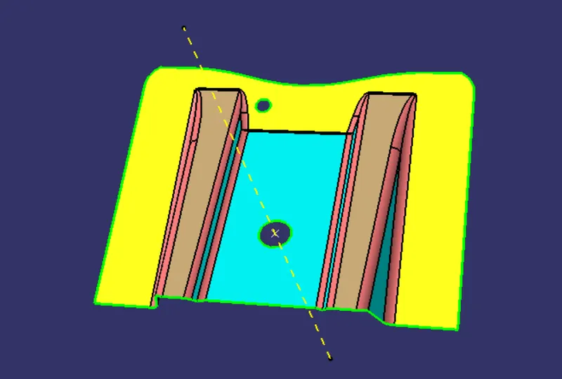
Dummy tooling axis.
Then create a plane with dummy tooling axis and yz plane. Then create a interscetin of model through yz plane as shown in below image.

Intersection line
Then create two parallel lines with the appliction of intersection use the point-point line command. Use those lines create a main toolsing axis by the application bisecting line command.
Here below the image show the main Tooling axis.
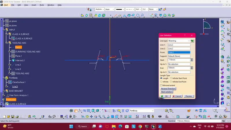
Tooing Axis
Once the Tooling axis create now we can make draft analysis of Class-A surface and the final plastic component.
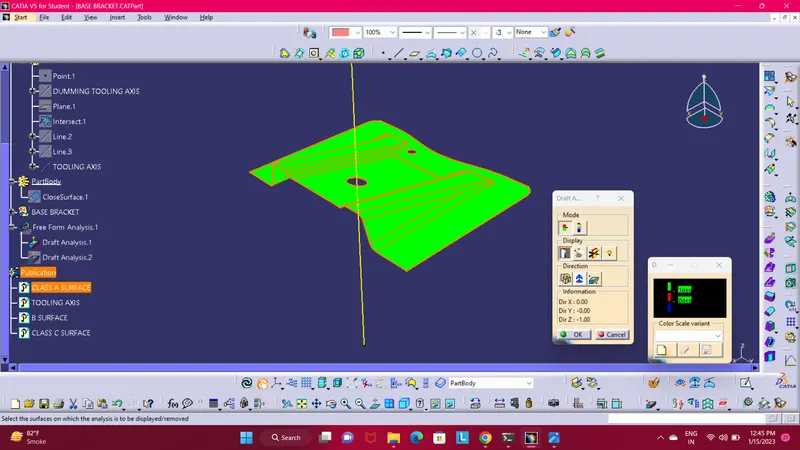
Draft Analysis of Class-A surface.
In the above image we are able to see the draft analysis of class-A surface. With the help of draft analysis command we can easly make draft analysis.
First apply a draft analysis command from mode section choose first one as shown in above image., then in display opt allow first opt to activate show/hide colur scale,
and the in last direction opt select the seconf opt compass then use fit all in command so you are able to see the compass as show in below image highlight in red.
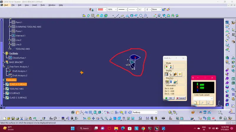
Compass
Then drag the compass to tooling axis and align to tooling axis line. Below the show alignment of compass and tooling axis image.
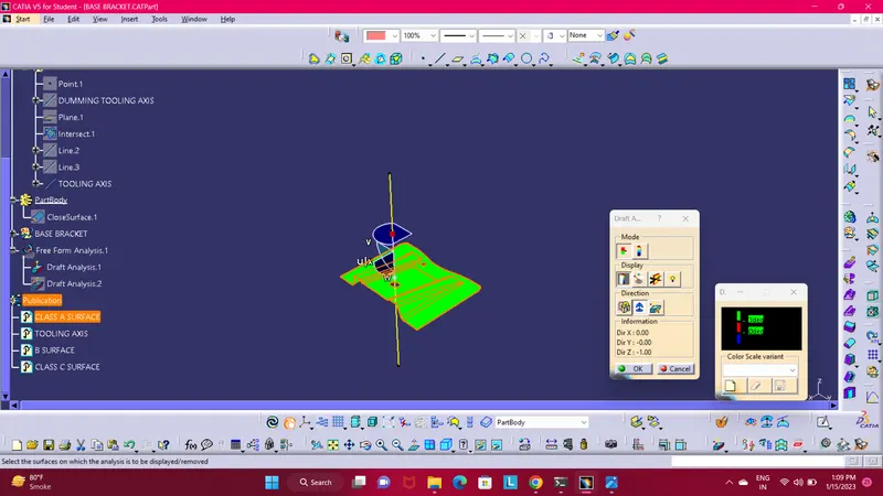
- Screenshots of the solid model with the proper color code of the draft angle in various orientations (Isometric, Front, Side, and Top View)
ISOMETRIC VIEW.
FRONT VIEW.
SIDE VIEW.
TOP VIEW.