Week 8 - Challenge 1 - Base Bracket Design
Importance of Draft in Plastic Designing:
Most Parts Require a Draft Angle of 1½ to 2 Degrees. This is a rule of thumb that applies to molded parts with depths of up to 2 inches. With this size, a draft of about 1½ degrees is enough for easy release of parts from the mold. This helps to prevent damages to the parts when the thermoplastic material shrinks.
Most Parts Require a Draft Angle of 1½ to 2 Degrees. This is a rule of thumb that applies to molded parts with depths of up to 2 inches. With this size, a draft of about 1½ degrees is enough for easy release of parts from the mold. This helps to prevent damages to the parts when the thermoplastic material shrinks.
Draft Analysis:
The draft analysis technique is used to analyze whether our part model created in CAD is manufacturable based on the draft condition applied. Here the part should get easily removed from the panel dies (in case of Sheet metal part) or Mold (in case of plastic)The Draft Analysis allows the user to easily analyze a part for proper draft angle. A Draft Angle describes the amount of taper for molded or cast parts perpendicular to the parting line.
Step1: For Draft Analysis we need Class A suface. Before Doing Draft analysis the View mode should be in Shading With Material.
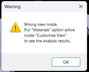 <-- This warning Will be shown if the view mode is wrong.
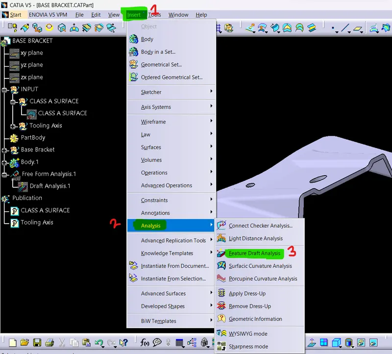
Step 2: Next Find Feature Draft Analysis from Insert as shown in Below Picture.
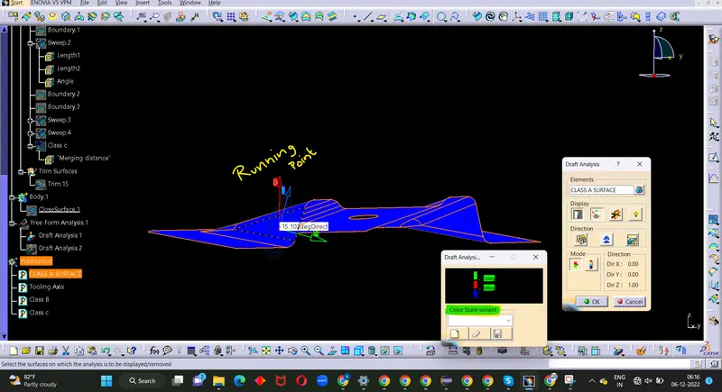
Step 3: Analys color Scale and Point Running Analysis, By Point Running analysis we can fing the draft whaer ever we are placing the point on the surface. Color variant shows the range of angle of the surface.
Tooling axis:
The direction in which the mold or core and cavity opens is the tooling axis.
Step 1: We can Create a dummy Tooling axis will be directly created using point-direction command.Checking possibilities (clearances) in all the directions of axis and find what are the problem creation parts of the component or model.
Step 1: We can Create a dummy Tooling axis will be directly created using point-direction command.Checking possibilities (clearances) in all the directions of axis and find what are the problem creation parts of the component or model.
Step 2: Then Create Plane at center point of the DUmmy Tooling Axis and Intersect the Class A at the plane and a sketch will be created along the suface.
Step 3: In the Scketch we have to find which are the edges may creates problem while clearence, then Bisecet those Two lines and create the Tooling axis to that.
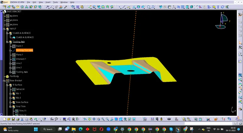
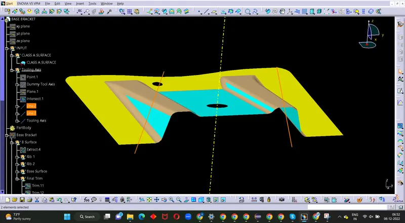
Tooling axis is used to create Class C Surface.
Publication:
Publication is used to make easily accessible of the published components.
Screenshots of the solid model with the proper color code of the draft angle in various orientations are attached as PDF file and CATpart also in Zip Format.