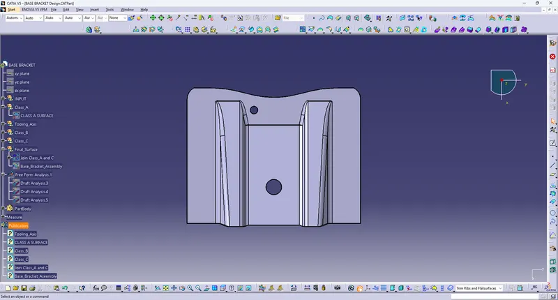
Week 8 - Challenge 1 - Base Bracket Design
Week 8 - Challenge 1 - Base Bracket Design
OBJECTIVE
- To Create or Develop Class B and Class C Surfaces of Base Bracket from the given Class A Surface.
- To Determine the Tooling Axis for the component.
- To Analyse Base bracket by featured Draft analysis in Catia V5
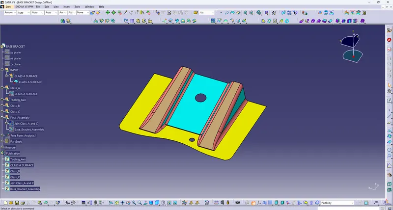
- Shown Screenshot is given Class A surface from the Design consideration team.From the surface create a centre point of the surface and add axis system from the point.
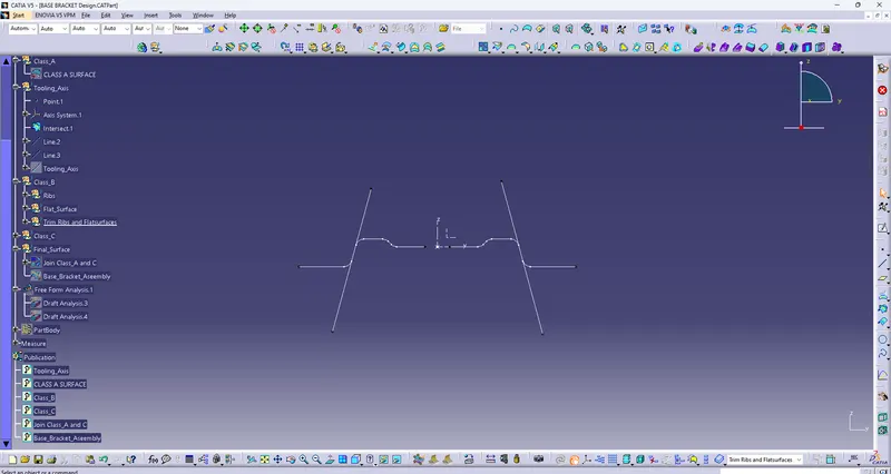
- Consider the possible axis for the component,i determine YZ axis. to create intersection of the surface in YZ axis.
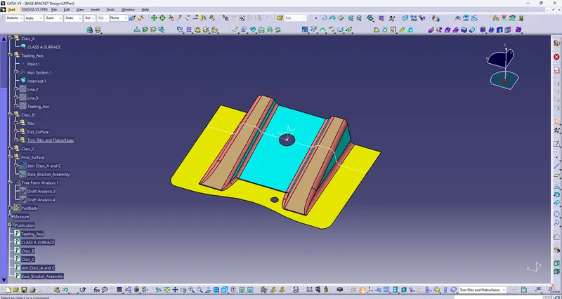
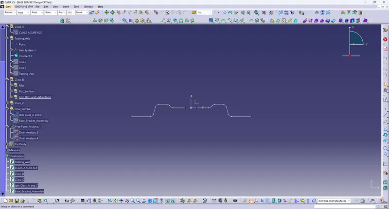
- From the Intersection of the surface,Boundary of the surface create line of two inclined edges of the surface.
- From these two lines and centre point, Bisecting Line is created and define as a Tooling Axis.
- A line segment bisector divides the line segment into 2 equal parts. It passes through the midpoint of the line segment.
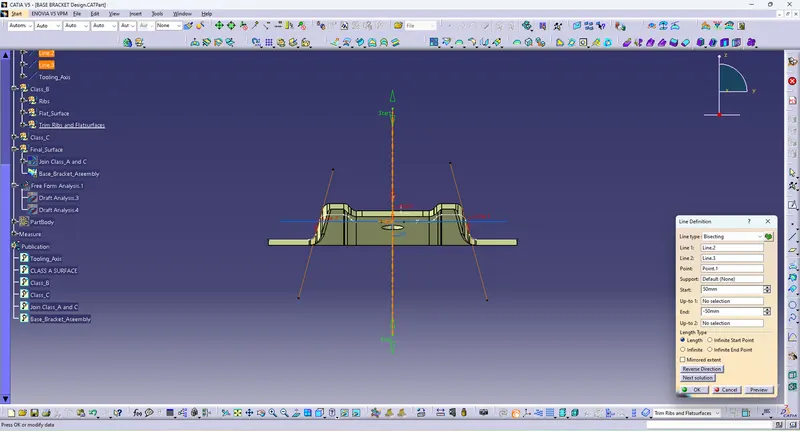
Screenshot is shown Bisecting line or Tooling Axis
- From the created Tooling Axis, Considered Reference axis and Develop Class B and Class C Surfaces.
- Class A surface is customer View or Outer present of the component.
- Class B surface is Design Engineer view of creating Screw or Boss, Mounting Clip and Etc of the component.
- Class C Surface is Possible Draft of the component to Eject from the Core and Cavity (Draft angle is commonly in design consideration is 3 Degree)and Thicken of the component is 2.5mm.
Class_B Creation
- From the class A surface Extract two Ribs, Flat Surfaces.
- Extract Ribs and FlatSurfaces is Untrim and Extrapolate 10mm of each ribs and Flat Surface
- Trim each Surfaces, of Ribs and Flat surfaces.
- Then Offset to 2.5mm, Because of Base Bracket thicken is 2.5mm
- After Offset, Trim both Ribs and Flat Surfaces.
- Fillet Each Edges of the surface. by Measure of Class A surface.
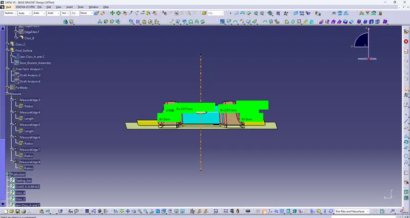
- By filleting the edges of the surface, should be considered Distance between Class A to Class B (Should be 2.5mm on every edges of the surface).
- For Inward Fillet,Radius of the curve is 3mm minus the Distance of Class A to Class B 2.5mm and Resultant fillet radius is 0.5mm
- For Outward Fillet, Radius of the curve is 3mm Add the Distance of Class A to Class B 2.5mm and Resultant fillet radius is 5.5mm
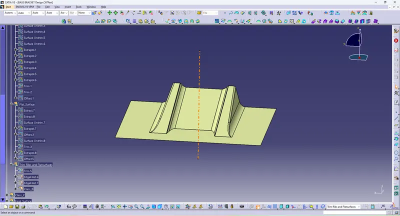
Screenshot shown as Class B surface
Class_C Creation
- From the Class A surface, Create Boundary of the surface
- Then Using Sweep command, Create Class C surface at 3 degree of Draft angle and distance of 15mm in the Tooling axis Direction.
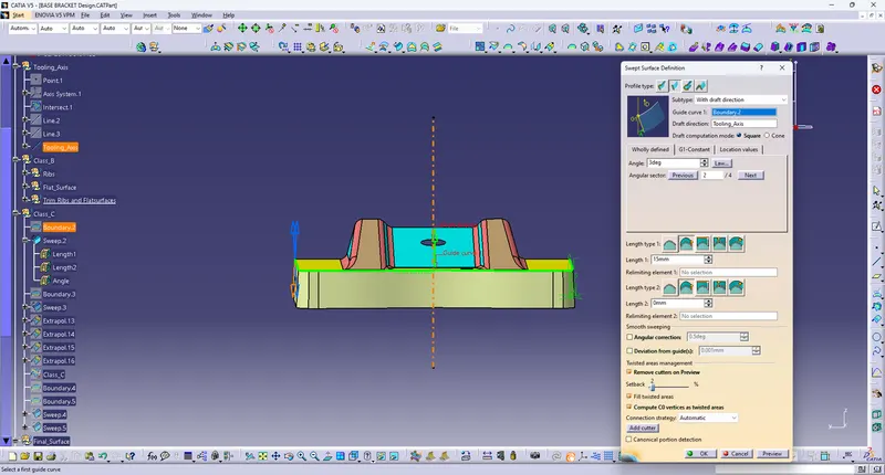
- Then as same Sweep command Create surface of Two Holes at Inward Draft angle 3 degree and distance 5mm in the Tooling axis direction.
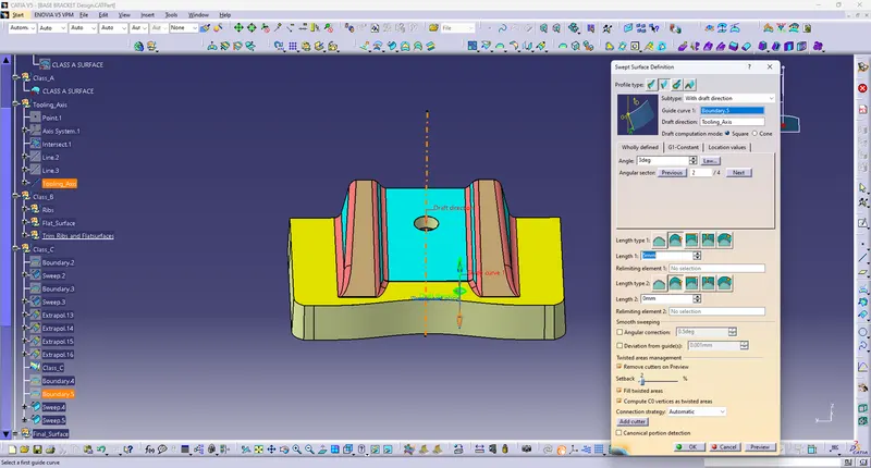
Screenshot Shown as Sweep command created for two Holes.
- Join the Class A and Class C surfaces.
- Then Trim both Join (Class A & C Surfaces) and Class B.
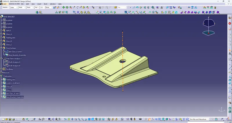
Screenshot of Base Bracket design (Class A,B and C)
Draft Analysis of Base Bracket
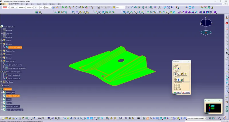
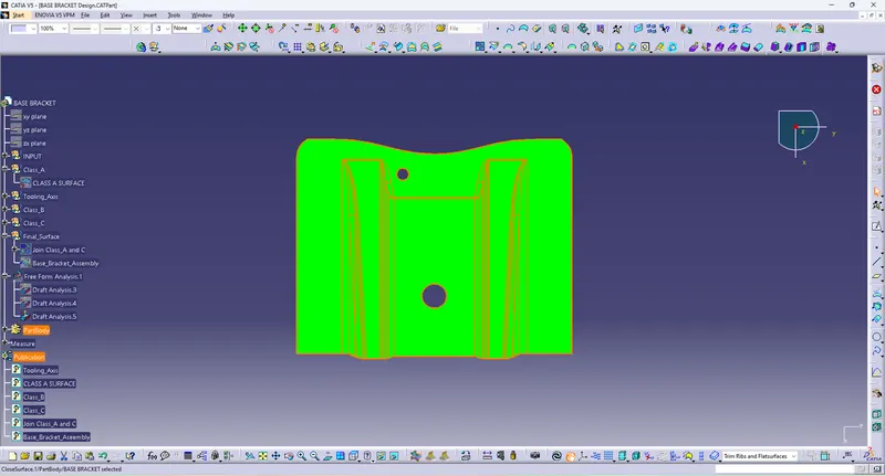
Screenshot of Class A surface
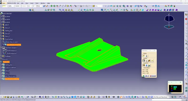
Screenshot of Complete Base Bracket Component (Class A,B and C )
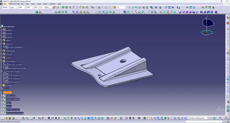
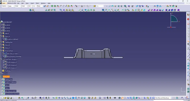
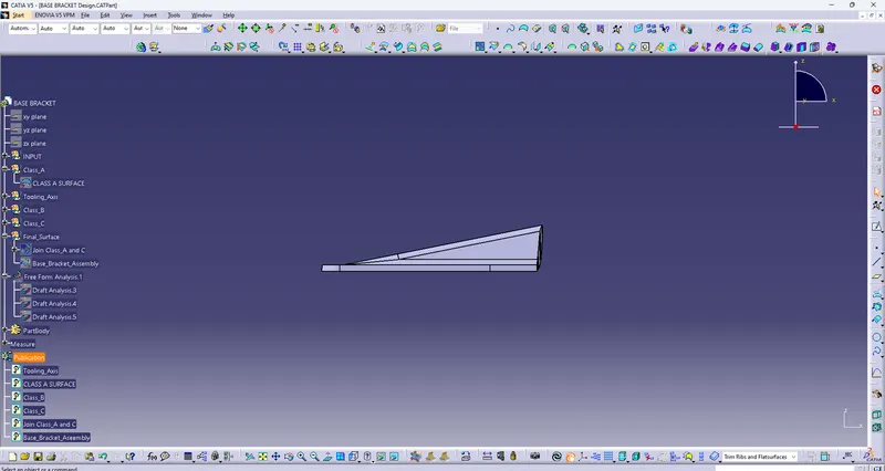
Screenshots of the solid model with the proper color code of the draft angle in various orientations (Isometric, Front, Side, and Top View)
Isometric View
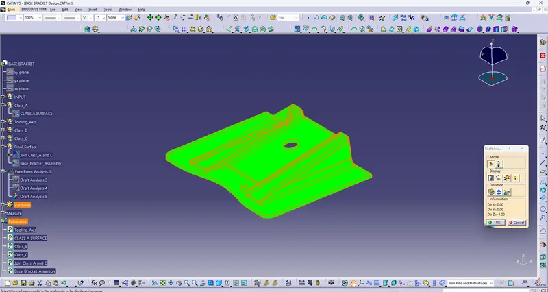
Front View
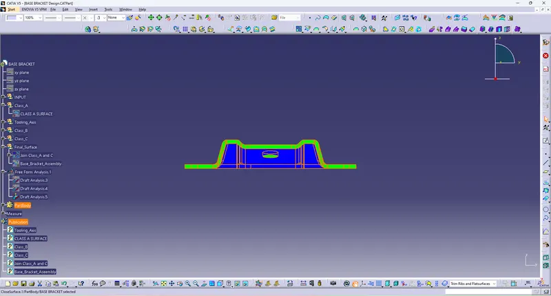
Side View
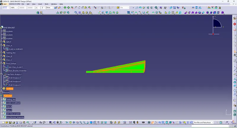
Top View