Week 8 - Challenge 1 - Base Bracket Design
DESIGN A BASE BRACKET
AIM - To create a Base Bracket Plastic Component through a given Class A Surface and perform Draft Analysis on the final plastic component.
objectives
- Creation of Tooling Axis.
- Creation of Class B and Class C surface.
- Creating a solid part out oF a surface modeling.
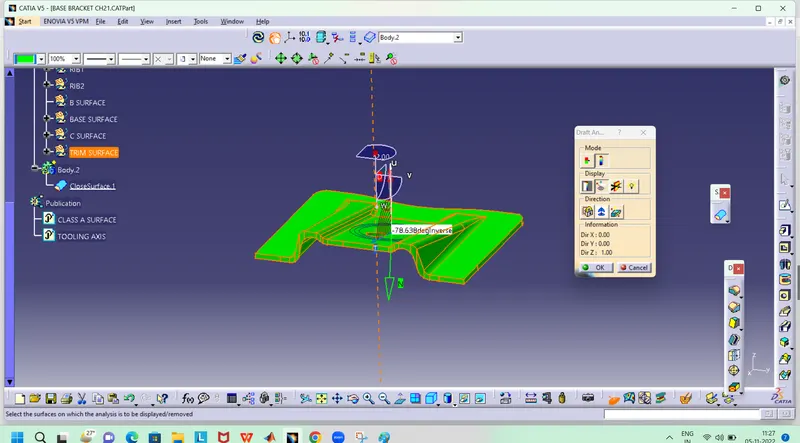
- Draft Analysis of Class A surface and final plastic component.
CLASS A: Following surface is given as the input for the component creation.
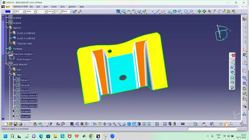
CREATE A TOOLING AXIS
- Create an intersection of CLASS A surface with ZX plane and from the intersection create the tooling axis as shown below.
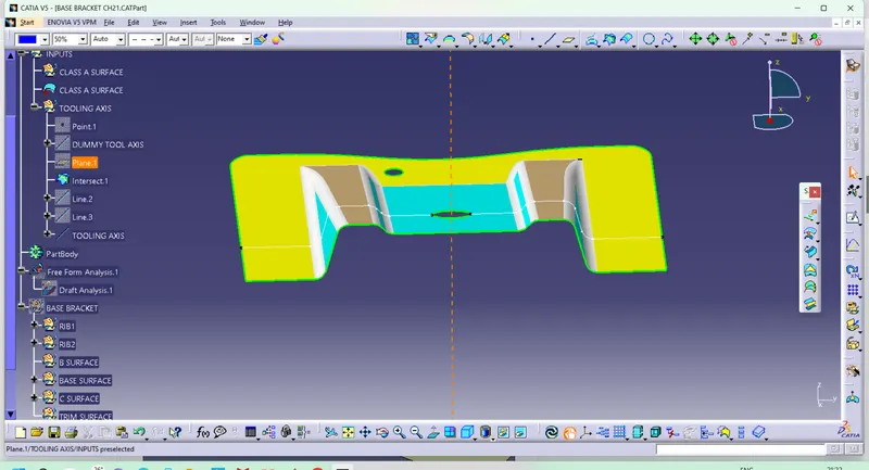
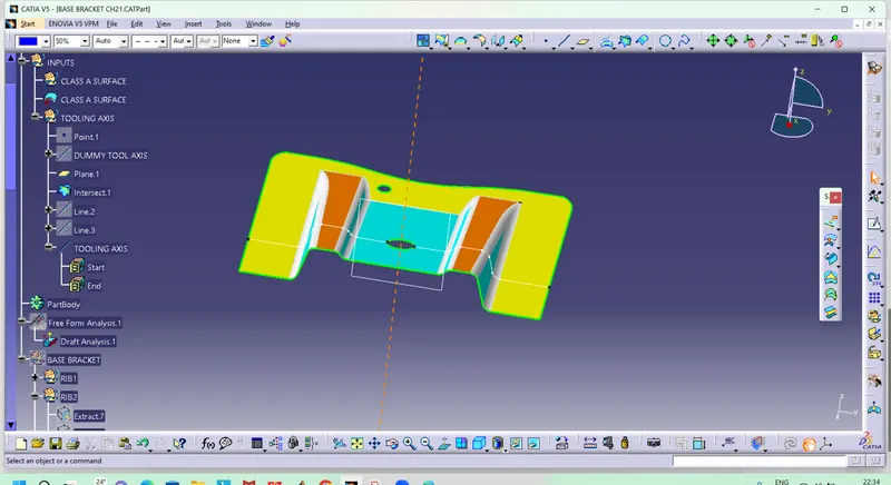
- Create a bisecting line using the lines shown above.
CREATING CLASS B SURFACE
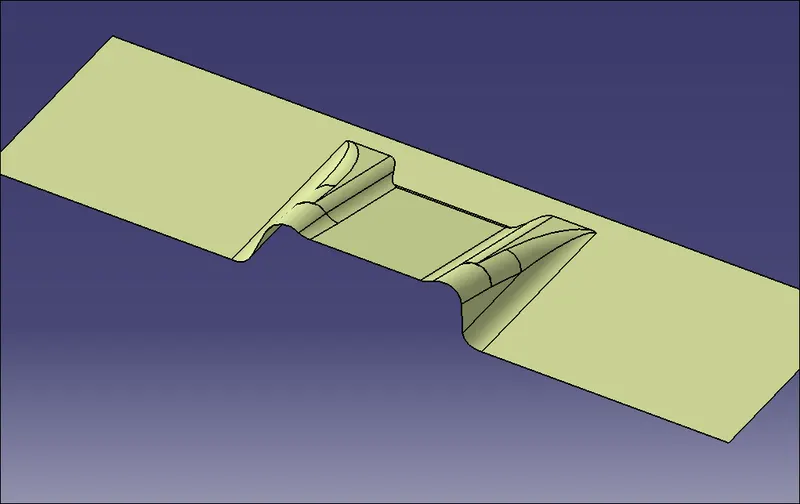
- Now for Class B creation, we have extracted surface from Class A and untrimmed them to obtain the original parent surface.
- These surfaces are then offset to the required thickness.
- After offsetting, all the surfaces are trimmed into the required shape.
- Required fillets are given to the surfaces.
CREATING CLASS C AND C + A
- For creating this surface we have extracted the boundry of Class A using multi-extract and then converted to smooth curve.
- Now this smooth curve is swept along the draft direction with a 3deg draft.
To make sure that there is not any open boundry between class A and class C, we have used join option to created the single body. This is done to make sure that the parting line doesn't lie between the these two surfaces.
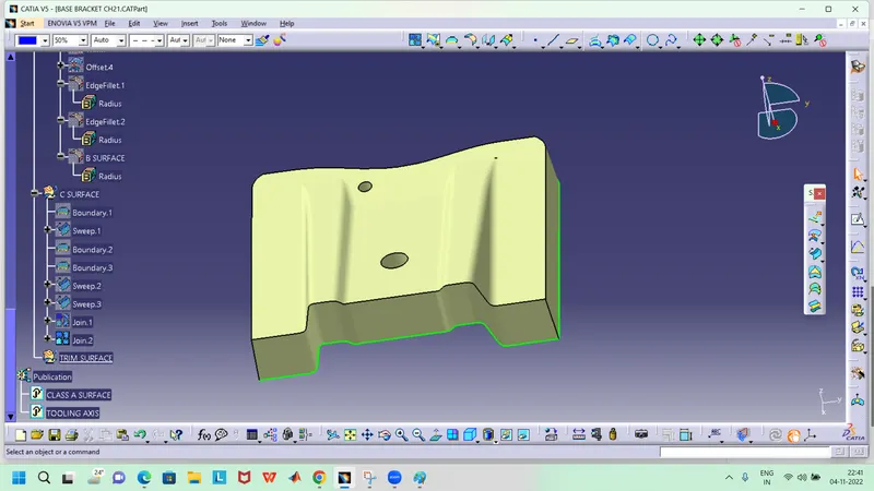
CLASS A+B+C SURFACES
For this we have trimmed the above shown surface with the Class B surface using trim feature.
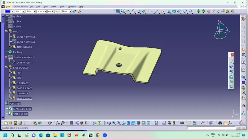
CLOSING SURFACE
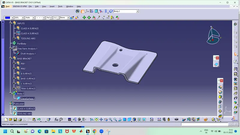
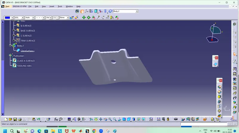
DRAFT ANALYSIS
CONCLUSION
Thus the base bracket plastic component has been designed using the given class-A surface.