Week 8 - Challenge 1 - Base Bracket Design
Objective:
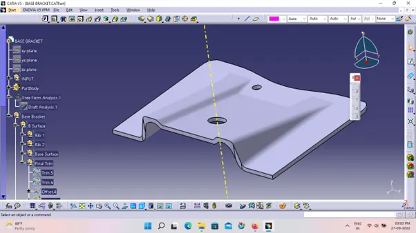
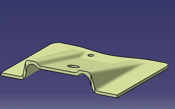
The main objective of this challenge is to create the Base Bracket Plastic component through the above-given Class-A surface, by giving the 'Tooling axis' and 'Draft analysis' to the class-A surface of the base bracket.
Tooling Axis:
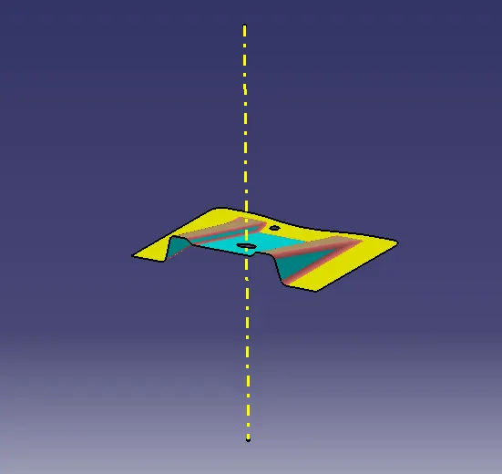
Tooling axis represents the path of the tool or core used while producing the part. We should take tooling axis in consideration while designing the part and proceed accordingly.
We should keenly observe and study the class A surface to create the 'Tooling Axis' for the component, for the above-given base bracket Z-axis is the best suitable tooling axis.
Draft Analysis:
It is the analysis process which informs us if the given design can be manufactured using the given tooling axis.
To perform draft analysis, click on Insert >>Analysis >> Feature Draft Analysis
Once the draft analysis toolbar is opened, go to the display block and select the 'Analysis under the running point' command to check the angle for different sides (ribs and inclined plane angles) on the class A surface. The color scale on the bottom visualizes, whether the draft angle meets the requirements or not (3 deg) by indicating the colors Green, Blue and Red. Once the draft angle analysis was done, we need to align and fix the compass to the tooling axis of the class A surface.
Class B Surface:
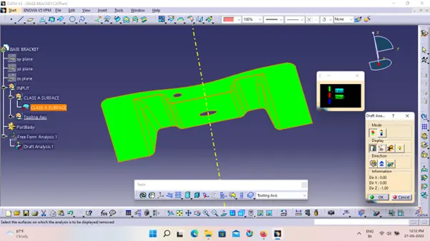
Class B surface is the inner engineered surface which is derived from the given Class A surface. It is generally created by off setting the given class A surface up to the thickness value.
Class C Surface:
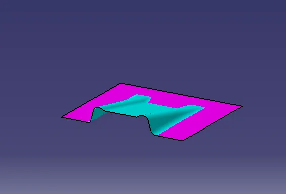
It is a surface which basically joins the class A surface to the class B surface. It is generally made using the sweep command. Class surface’s boundaries are swept through the Class B surface and a closed surface is obtained which is called the Class C surface.
Solid Body:
A solid body is created using closesurface command.