Week 8 - Challenge 1 - Base Bracket Design
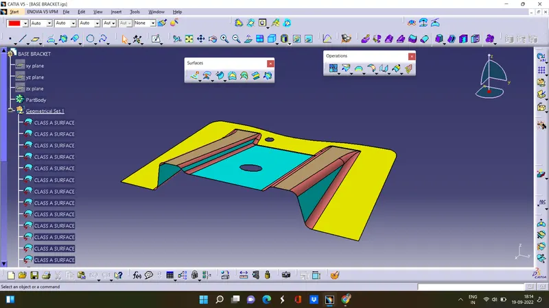
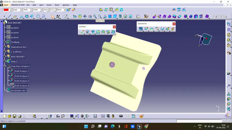
AIM: to make a model from the provided class-A surface.
INTRODUCTION:
CLASS-A SURFACE: a surface made by the designer which is given as an input to the plastic modeler to work on. It is aesthetic surface and the outer most surface.
CLASS-B SURFACE: a surface below a certain thickness from the class-A surface is class-B surface. This is the surface that contains engineering aspects of a model.
CLASS-C SURFACE: a surface that joins class-A and class-B surfaces is class-C surface.
METHODOLOGY:
In this model we have focused on the following things:
- Tooling axis
- Draft analysis
- Class-B surface
- Class-C surface
- Making a solid model from surface.
Following tools were used to reach the final step:
- Extract
- Un-trim
- Trim
- Extrapolate
- Offset
- Edge fillet
- Boundary
- Sweep
- Join
- Close (part design)
FOR TOOLING AXIS:
- First ensure the class-A surface is properly joined and has no discontinuity on it. For this we can use boundary command or join command.
- Analyze the model manually or visually to see which direction is most suitable for tooling axis.
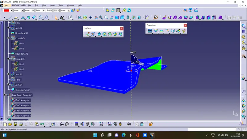
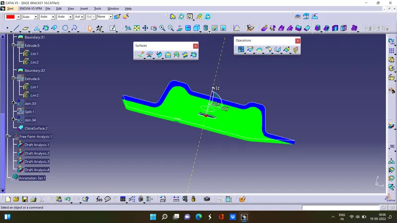
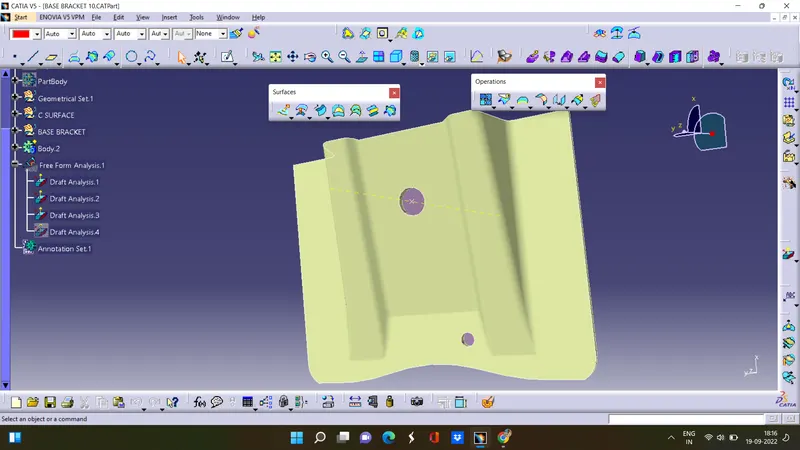
- As in 3D view we can see 2 holes and a flat surface, we can directly take the tooling axis perpendicular to that. But to be sure,let us analaze from all the views. The below images of the front side and top views shows the areas that we have to keep in mind while choosing tooling axis. As from X we cannot see one hole so we cannot take axis along this. In Y we cannot see any holes so here too we cannot take tooling axis. But in Z we can see 2 holes and flat surface so we can take tooling axis.