Week 8 - Challenge 1 - Base Bracket Design
Aim - To create the Base Bracket Plastic component through the given Class-A surface. To begin with, the tooling axis for the given Class-A Surface should be created meeting the requirements of the draft angle and at the end perform the Draft analysis on the model.
INTRODUCTION:
CLASS-A SURFACE: A surface made by the designer which is given as an input to the plastic modeler/ sheet metal designer to work on. It is aesthetic surface and the outer most surface.
CLASS-B SURFACE: A surface below a certain thickness from the class-A surface is class-B surface. This is the surface that contains engineering aspects of a model for example Ribs cutout.
CLASS-C SURFACE: A surface that joins class-A and class-B surfaces together is called as a class-C surface.
Report
A detailed report should be done explaining the draft analysis and the tooling axis creation.
An explanation should be given on the way of creating the tooling axis, particularly the Bisecting method.
Draft Analysis:- Draft is a taper applied to the faces of the part that prevent them from being parallel to the motion of the mold opening. This keeps the part from being damaged due to the scraping as the part is ejected out of the mold, to do that the analysis is done and known as Draft Analysis
Tooling axis: The direction in which the mold or core and cavity opens is called as the tooling axis.
Tooling axis creation
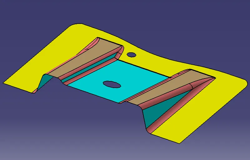
As in 3D view we can see 2 holes and a flat surface, we can directly take the tooling axis perpendicular to that but In order to make a correct tooling Axis we need to do an visual inspection first and see from all direction where will the problem occur while producing the part so as doing the visua inspection there will be be some faces that need draft angle in order to withdraw the part
Visual Inspection
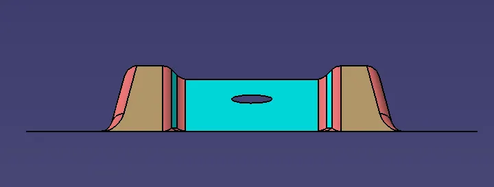
As we look from X axis side we are not able to see all faces same as we see from Y direction but as we see it from Z direction we are properly able to see the whole part and the slant faces as well
X-Direction
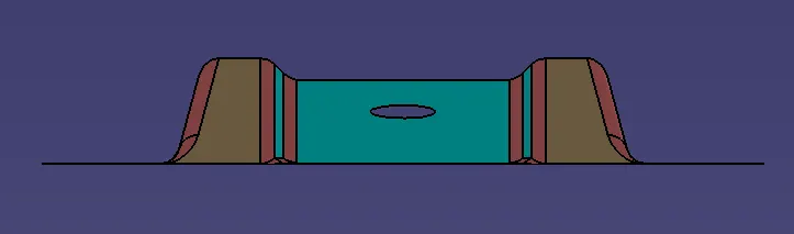
Y-Direction
Z-Direction
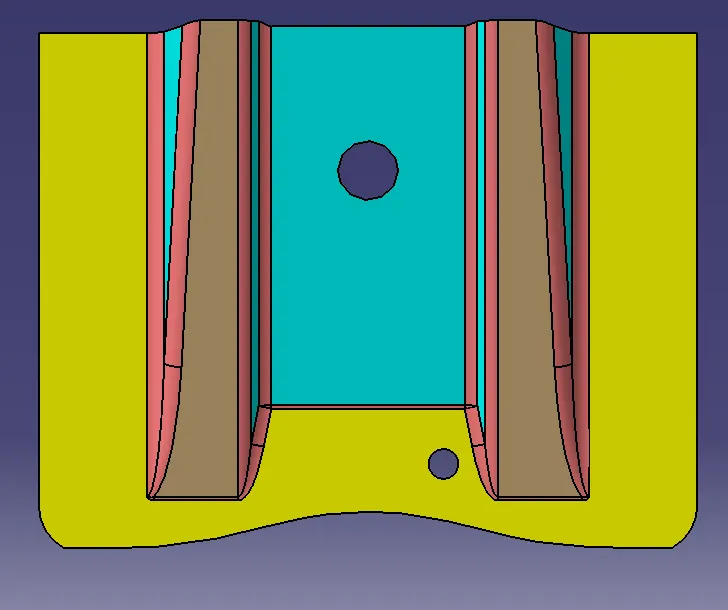
As we done with the visual inspection we need to make a dummy tooling axis line for reference and in order to make a Tooling axis we need to creat a point first
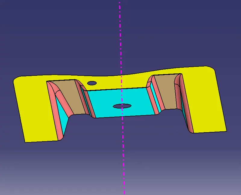
Use the tool Intersection curve to make an intersection and use the line command to make the two line and after creating the 2 line use the bisecting line command to make a bisecting line between the 2 line and this is going to be the tooling Axis for the part
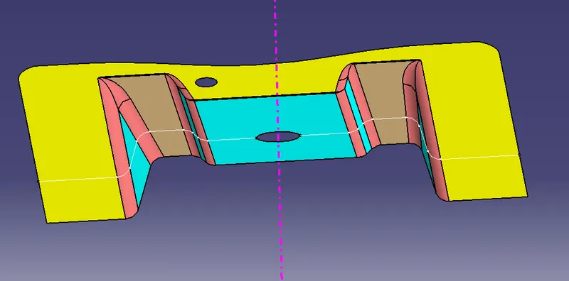
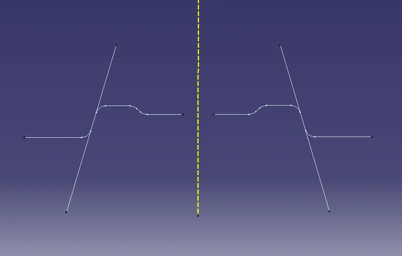
Tooling Axis
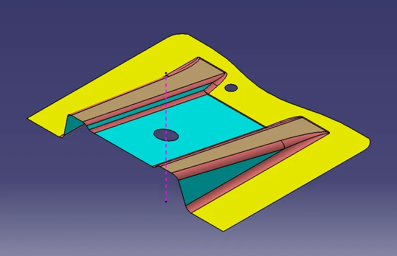
FOR DRAFT ANALYSIS:
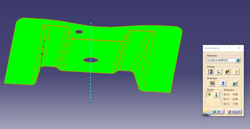
Go to insert< analysis< feature draft analysis.
Align the tooling axis with the compass.
Click on the surface and see that the surface is within the permissible limit of the draft values.
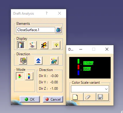
The surface should be green and in the column proper value (3deg) should be inserted as 3 degree which is minimum for Class A surface
Creation of Class B:
- Now for Class B creation, we have extracted surface from Class A and untrimmed them to obtain the original parent surface.
- These surfaces are then offset to the required thickness.
- After offsetting, all the surfaces are trimmed into the required shape.
- Required fillets are given to the surfaces.
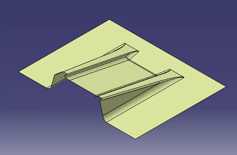
Creation of Class C:
- For creating this surface we have extracted the boundry of Class A using multi-extract and then converted to smooth curve.
- Now this smooth curve is swept along the draft direction with a 3deg draft.
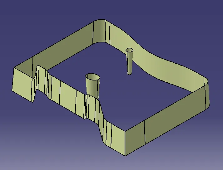
Final Trims:
Class A + Class C:
To make sure that there is not any open boundry between class A and class C, we have used join option to created the single body. This is done to make sure that the parting line doesn't lie between the these two surfaces.
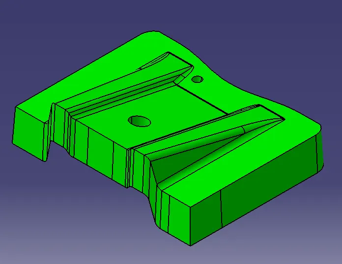
Class A + Class B + Class C:
For this we have trimmed the above shown surface with the Class B surface using trim feature.
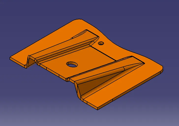
Go to the part design and select the surface and use the closed surface command to convert it into the solid plastic part
Draft Analysis for Solid Plastic Part
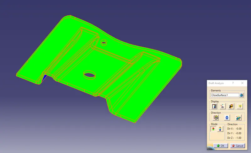
Colour Scheme
Screenshots of the solid model with the proper color code of the draft angle in various orientations (Isometric, Front, Side, and Top View)
Isometric View
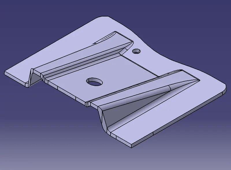
Front Side
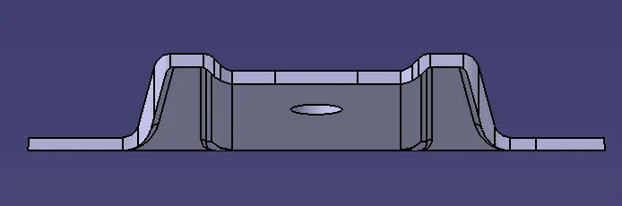
Side View
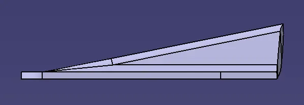
Top View
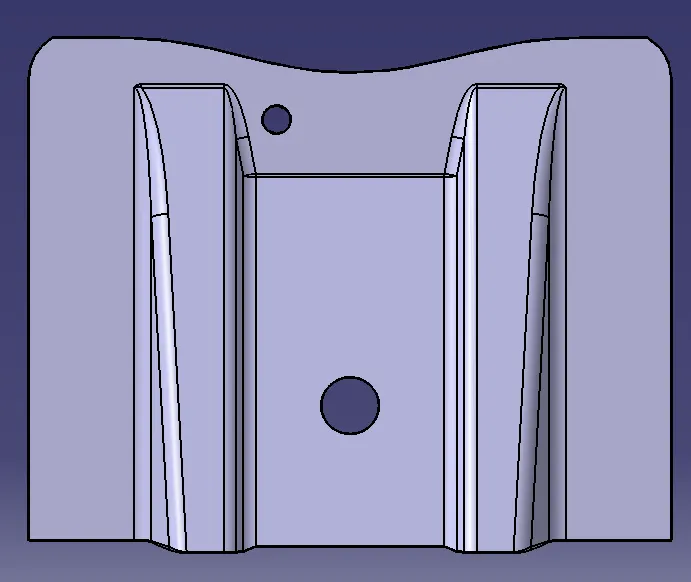
Tree Structure
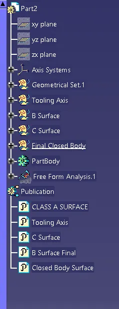
Please find the attached part file for your review