Week 8 - Challenge 1 - Base Bracket Design
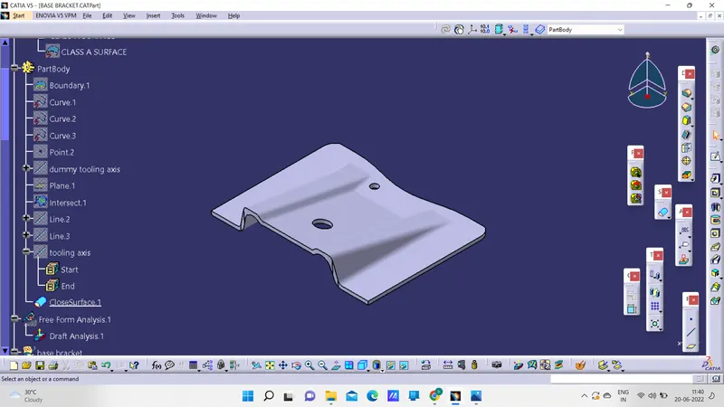
Aim: To create a Base Bracket Plastic Component through a given Class A Surface and perform Draft Analysis on the final plastic component. Objectives: • Creation of Tooling Axis. • Creation of Class B and Class C surface. • Creating a solid part out of surface modelling. • Draft Analysis of Class A surface and final plastic component.
Tool Used: CATIA V5
Introduction: In this project we are designing a base bracket using given class A surface. The approach includes creation of Class B surface keeping 3 mm thickness in mind for the complete component. The design also included Class C creation from the given parent surface.
Constraints:
• NO CHANGES IN CLASS A ARE ALLOWED.
• PART THICKNESS CANT DEVIATE BY MORE THAN ± 30%
• ALL DESIGN RULES SHOULD BE STRICTLY FOLLOWED.
• ALL SURFACES SHOULD BE CLOSED BEFORE CONVERTING TO SOLID.
• ALL FACES SHOULD MEET THE ALLOWED DRAFT REQUIREMENTS.
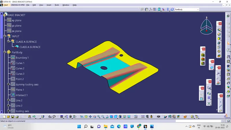
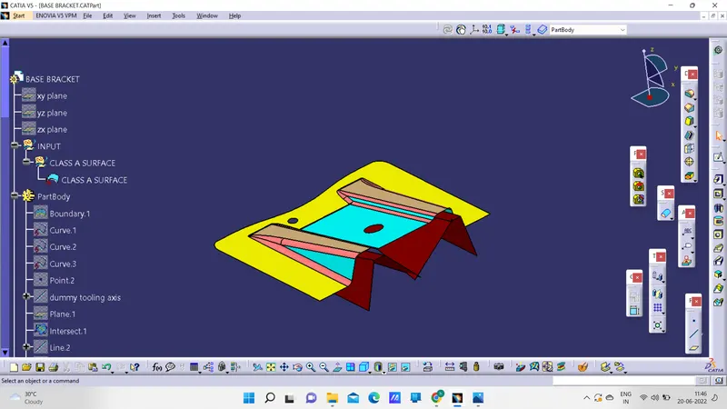
CLASS A: Following surface is given as the input for the component creation.
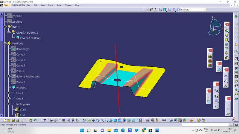
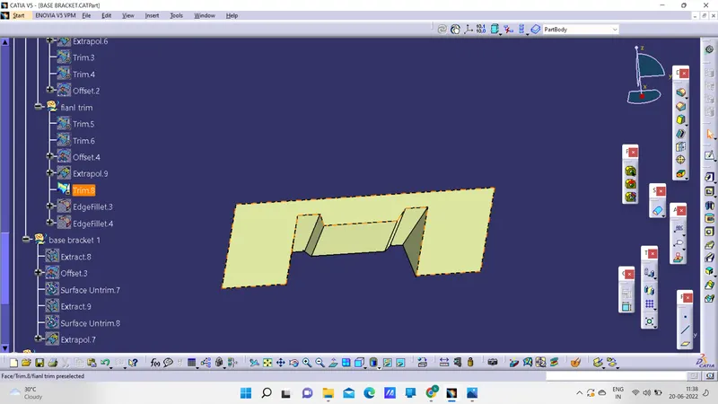
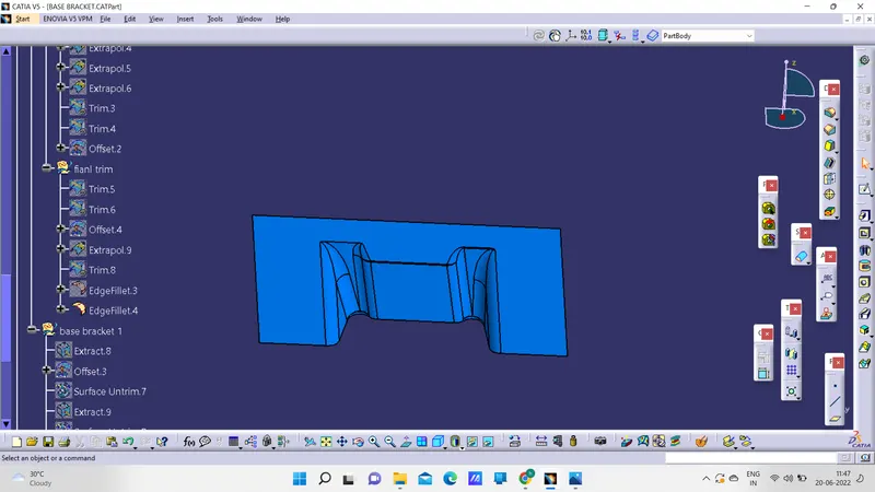
• Now for Class B creation, we have extracted surface from Class A and untrimmed them to obtain the original parent surface. • These surfaces are then offset to the required thickness.
Creation of Class C:
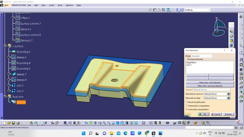
• For creating this surface we have extracted the boundry of Class A using multi-extract and then converted to smooth curve. • Now this smooth curve is swept along the draft direction with a 3deg draft.
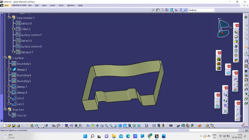
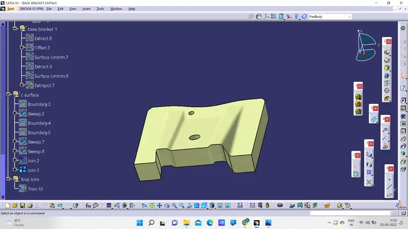
Final Trims: Class A + Class C: To make sure that there is not any open boundry between class A and class C, we have used join option to created the single body. This is done to make sure that the parting line doesn't lie between the these two surfaces.