Week 8 - Challenge 1 - Base Bracket Design
Tooling Direction :-
Tooling axis is the direction in which mold or core and cavity opens. The ejection of the part from mold depends on the draft. A zero draft can result in difficult or no ejection due to shrinkage. It is recommended to add a minimum of 0.5 to 1 degree of the draft for non-textured surface & 3 to 5 degree of draft for textured surfaces.
Procedure to create the tooling axis using bisecting method :-
following Class A surface is provided to design the base bracket plastic component.
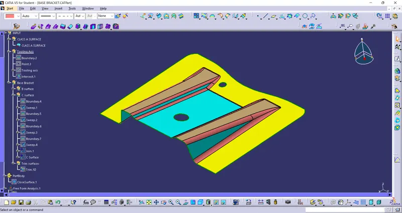
Point is created at the centre of a hole
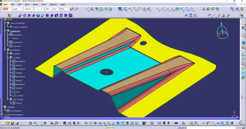
YZ Plane is created at the center of the hole and intersection of a surface is taken along the created plane.
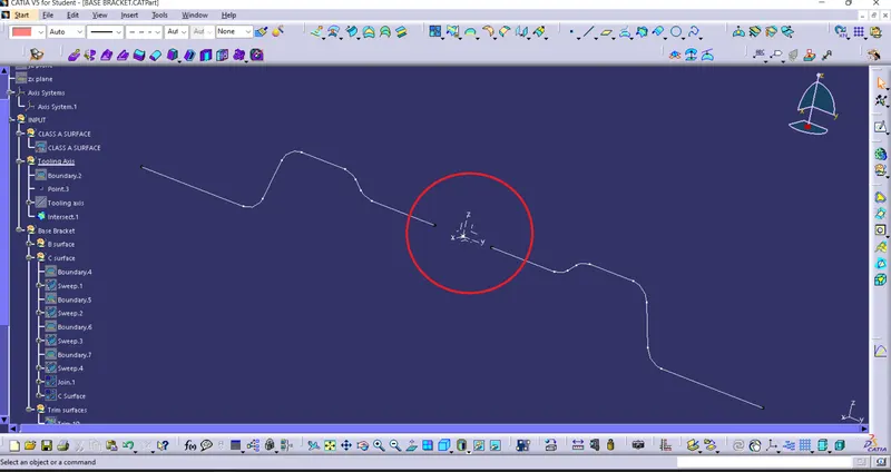
In this way we can create the tooling direction.
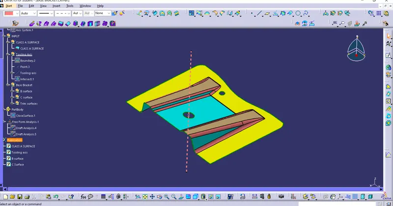
Draft analysis :-
Draft analysis is performed based on color ranges identifying zones on the analyzed element where the deviation from the draft direction at any point, corresponds to specified values. Minimum draft angle is considered as 3 degree.
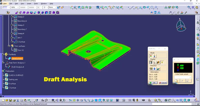
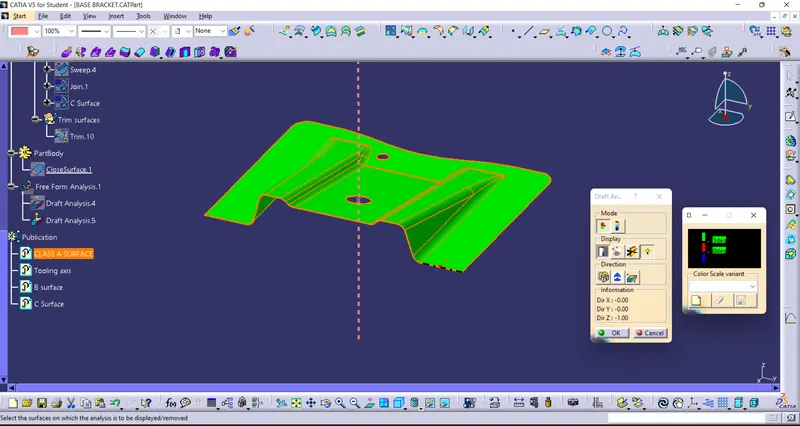
B-Surface :-
Class B-Surface is extracted from the A-surface and it is offseted at 2.5mm in downward direction.
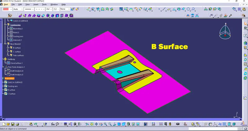
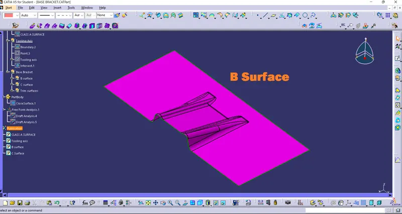
C-Surface :-
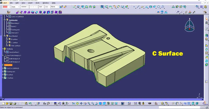
C-Surface connects the class A-Surface and B-Surface. It is created using Sweep command. Boundry of the class A-Surface is swept along the tooling direction.
Trim Surface :-
A & C-Surface are joined together then it is trimmed along the B-Surface.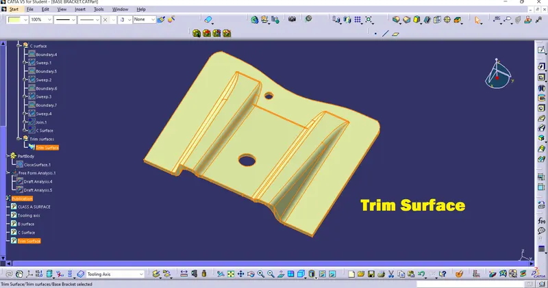
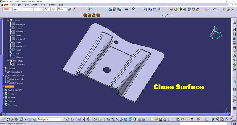
Final Solid Body :-
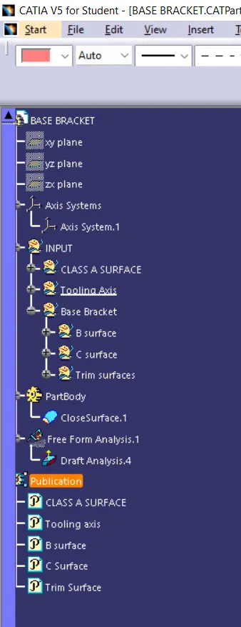
Tree Structure :-
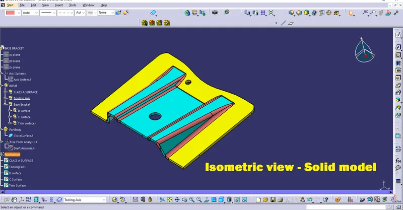
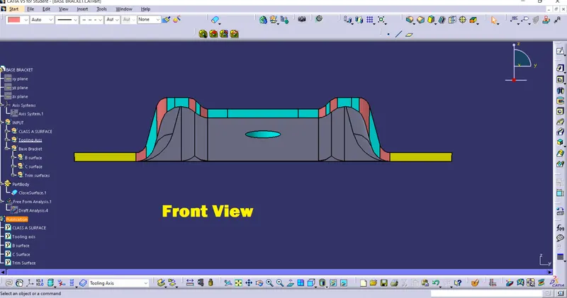
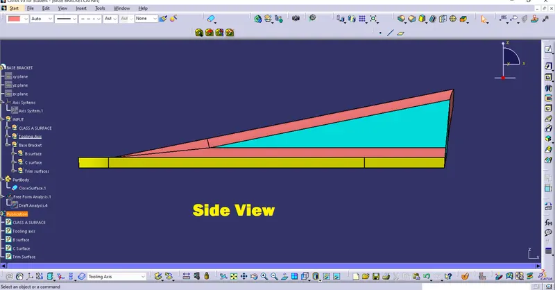
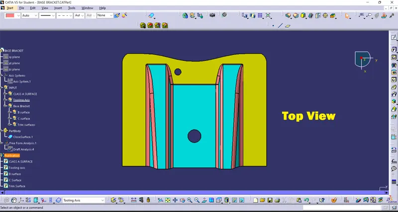
Solid Model in various orientations :-