Week 8 - Challenge 1 - Base Bracket Design
AIM
To create a Base Bracket Plastic Component through a given Class A Surface and perform Draft Analysis on the final plastic component.
OBJECTIVE
- To make sure that the model meets the requirements of the draft angle.
- To create the Tooling axis using bisecting method.
- To perform Draft analysis on the given Class A Surface.
- To create the required Class B and Class C surfaces.
- To obtain a solid body from the surface using Close Surface feature.
- To perform draft analysis on final plastic component.
CLASS A SURFACE
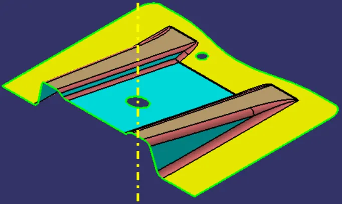
- Class ‘A’ surfaces are primarily used in the automotive environment and refer to those surfaces which are visible in a product. In other words: A - class surfaces are those aesthetic/free-form surfaces, which are visible to us (interior/exterior), and have an optimal aesthetic shape and high surface quality.
- The surfaces or regions which are visible nowadays are considered for Class-A modelling. It is one of the reasons why the importance of Class-A modelling is increasing day by day. Majority of the time this term is used in Plastic Part designs.
CLASS B SURFACE
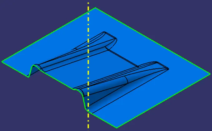
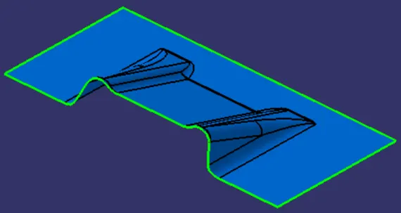
- The Class B surface is created from the Class A surface, keeping the thickness of the component in check.
- The Class B surface resembles an offsetted surface from the Class A.
CLASS C SURFACE
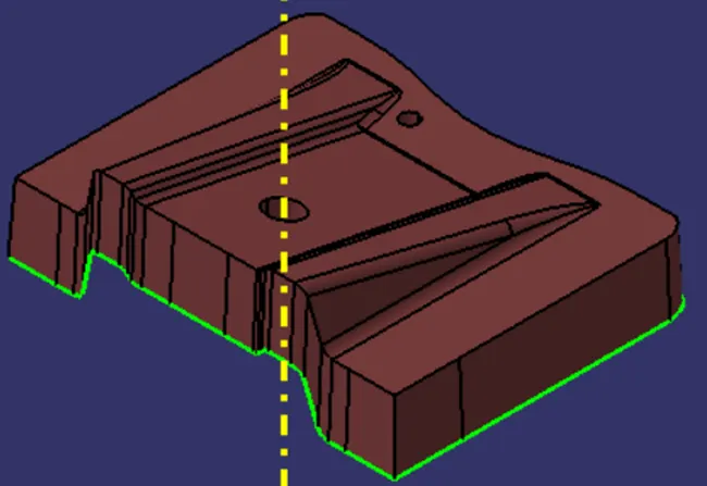
- The Class C surface is used to bind the Class A and Class B surface together in order to form a closed surface.
PROCEDURE
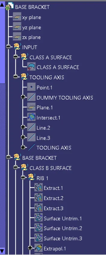
Creating Tool Axis
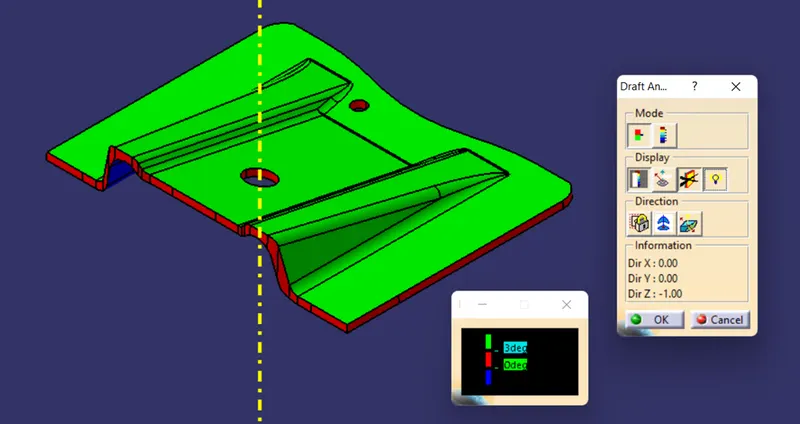
- Initially the given Class-A surface was imported and checked for any discrepancies in the boundary and performed draft analysis on it at 3-degree draft.
- A dummy Tooling axis was created using a reference point created on a hole of the given surface.
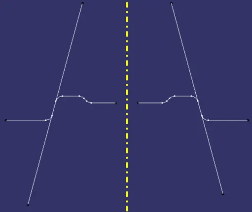
- Create an intersection of CLASS A surface with ZX plane. The lines which might cause trouble during the operation were identified and a reference line was created for each of the identified lines.
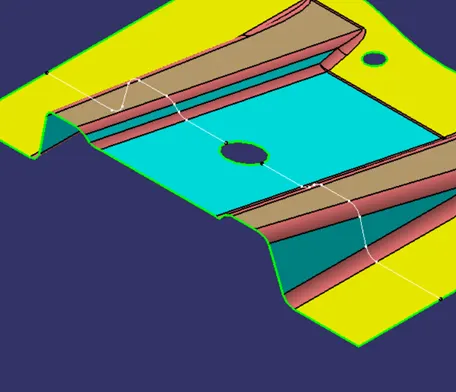
- Finally, a Tooling axis was created from these two reference lines using Bisecting option.
Creating Class B surface
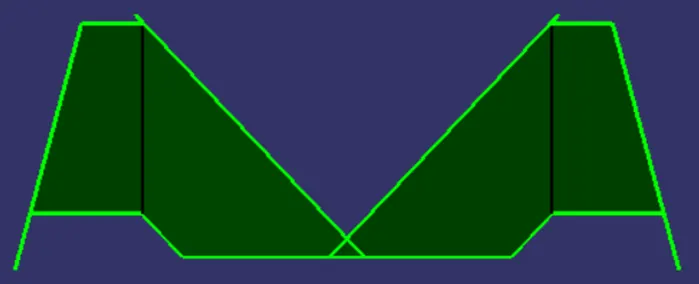
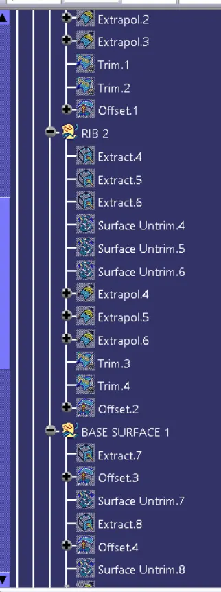
- Initially the ribs were created from the Class A surface.
- The required surfaces were obtained from the Class A surface using Extract command.
- These surfaces were further expanded using Untrim and Extrapolate commands
- The protruding surfaces were trimmed using the Trim command and a proper continuous surface was obtained.
- The same procedure was followed for the middle flat surface and surrounding area.
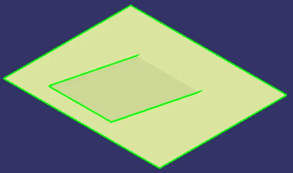
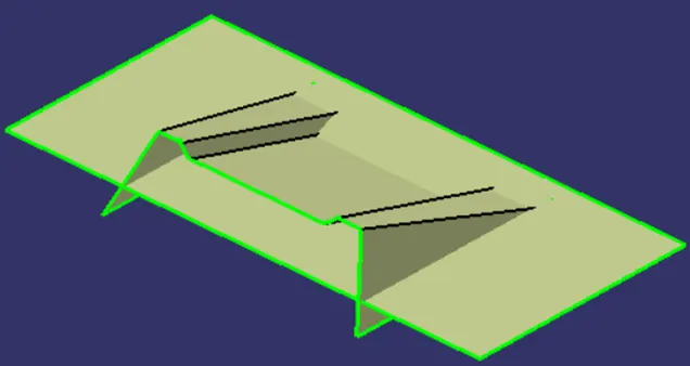
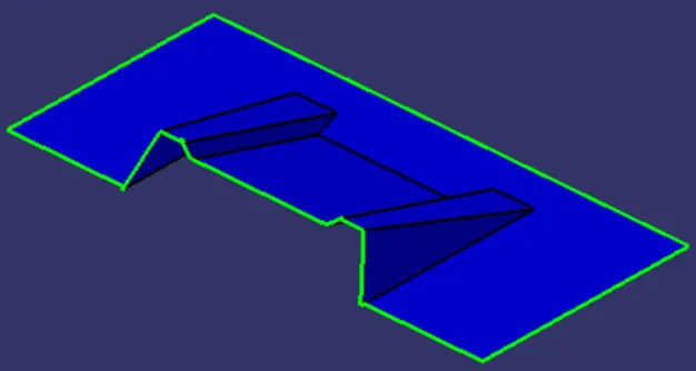
- These surfaces were offsetted according to the required thickness of the component.
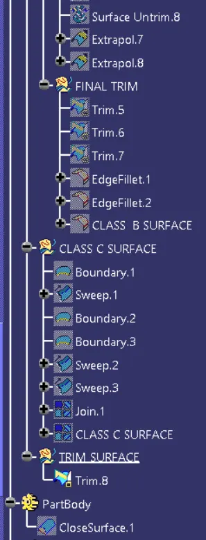
- Finally filleting the edges of class B surface considering thickness value to it.
Creating Class C surface
- The Class C surface connects the Class A and Class B surface.
- Initially the outline of the Class A surface was obtained using the Boundary command.
- The Sweep command was used along with draft direction, with a draft angle of 3 degree.
- Further the holes presented in the surface were created in the same manner.
- All the swept surfaces were finally attached to the Class A surface using the Join command.
- Further the holes presented in the surface were created in the same manner.
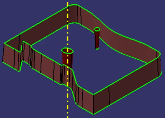
- All the swept surfaces were finally attached to the Class A surface using the Join command and obtained as CLASS C surface
Creating Solid Body
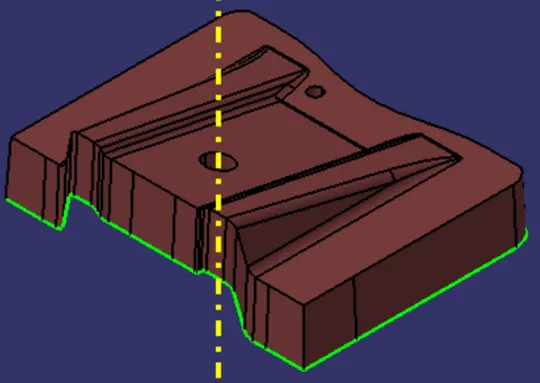
- Later, CLASS C and CLASS B surfaces were trimmed and forms the base bracket surface.
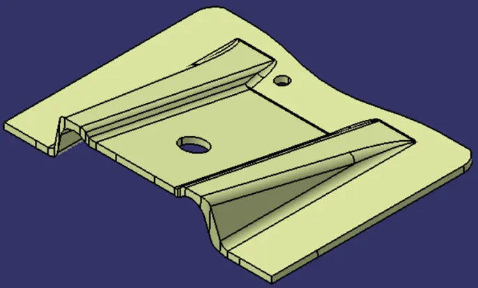
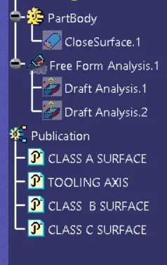
- Using the surface created, the solid component was obtained using the Close surface feature present in the part workbench.
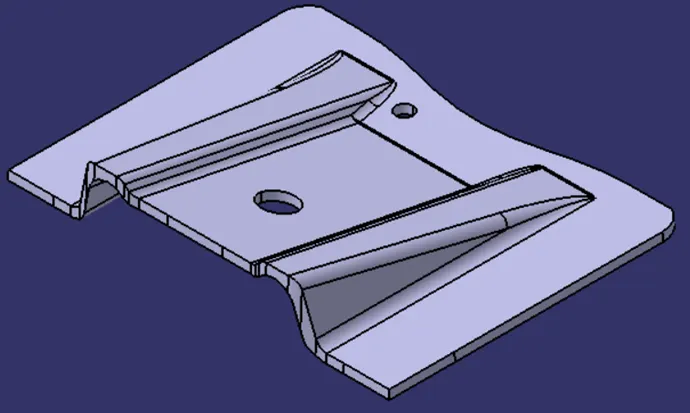
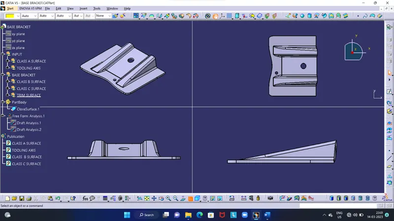
- The Tooling axis, Class A, B and C surfaces were published.
DRAFT ANALYSIS
- First, we should change model into material mode
- Go to insert and in analysis select feature draft analysis
- Align the compass along tooling axis
- Next click on the surface and see that the surface is within the permissible limit of the values
- The draft angle should be 3 degrees.
On given Class A surface
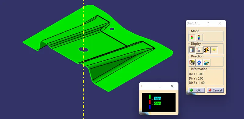
On obtained PART BODY
EXPANDED TREE STRUCTURE
CONCLUSION
- The creation of Tooling axis and Draft analysis were performed.
- The solid component was created from the surface geometry.
- The necessary screenshots and files were attached.