Week 8 - Challenge 1 - Base Bracket Design
WEEK 8 - CHALLENGE 1 - BASE BRACKET DESIGN
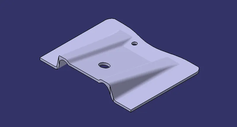
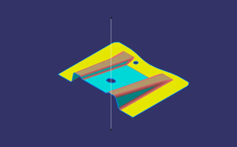
OBJECTIVE : To create the Base Bracket Plastic component through the given Class-A surface. To begin with, the tooling axis for the given Class-A Surface should be created meeting the requirements of the draft angle and at the end perform the Draft analysis on the model.
Thickness of Plastic Part - 2.5 mm.
GIVEN CLASS A SURFACE :
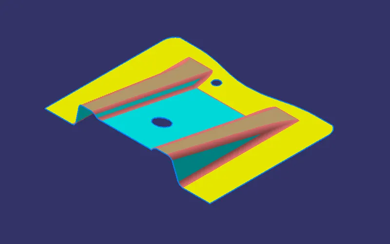
IMPORTANT NOTE :
- Tree Structure
- Ensure Proper Tree Structure
- Geometrical sets should have a proper name based on the sketches present inside of it
- All the sketches should be created under the Geometrical set
- Use the Close Surface feature to make a solid body from the surface.
- Publications: Use the publication option and publish the below
- Tooling Axis
- Class A, B, and C surface
BASE BRACKET DESIGN IN CATIA V5 :
TOOLING AXIS CRAETION :
A point was created at the center of the large circle, Using that axis system is inserted,using the ZX plane an intersection is to be made.
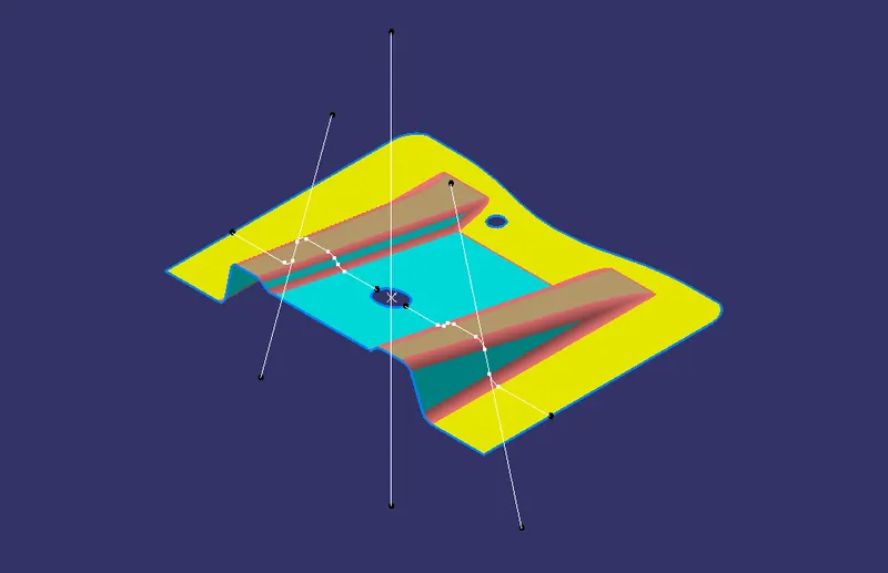
EXPLANATION ON BISECTING METHOD:
Bisecting method is basically use to find the proper tooling axis using the dummy tooling axis. In Bisecting method, bisecting line is used which either bisect the two line or it will show error which means the two lines are parallel to each other. In order to know whether the particular surface is toolable or not we intersect the surface with the respective plane and get a sketch which consist of two lines and with the help of bisecting line option we bisect the line which creates a line at the mid point of the two lines. Like wise we create tooling clearing axis for x and y which will be used to create the main tooling axis using the bisecting line option in in the line comand.
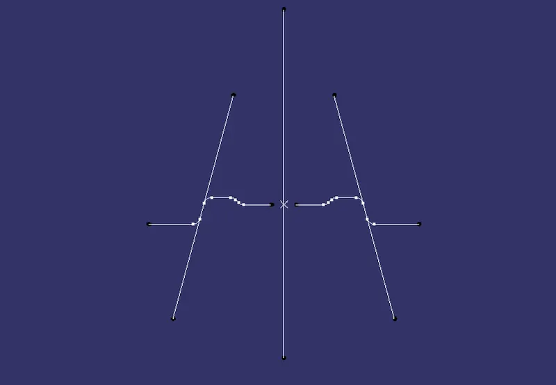
Two lines need to be created from the points-take any two of the incline lines as reference,Create a bisecting line for the inclination lines,
The tooling axis is the tool movement axis (core/cavity).
This axis will decide the draft direction.
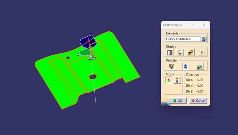
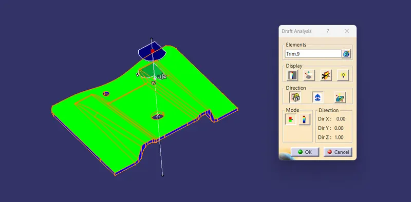
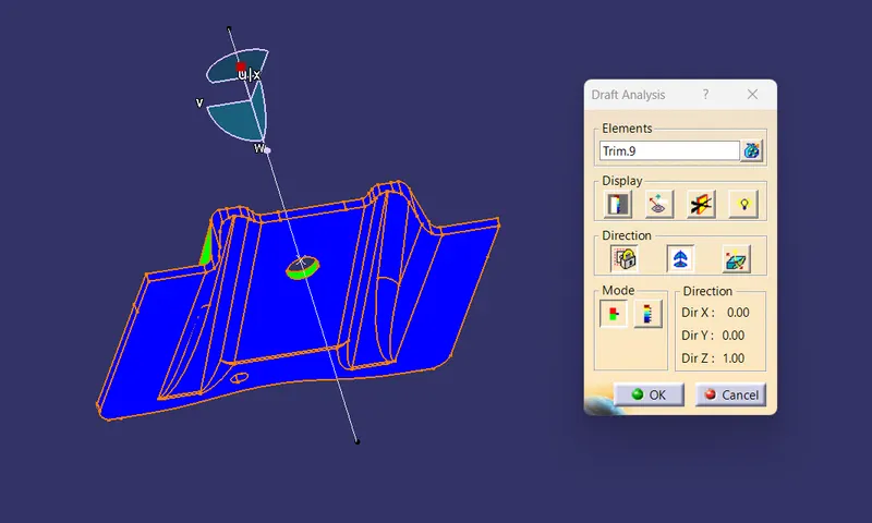
DRAFT ANALYSIS :
- CLASS A SURFACE
- FINAL PLASTIC COMPONENT
SOLID CAT PART IN CATIA V5 :
- ISOMETRIC VIEW :
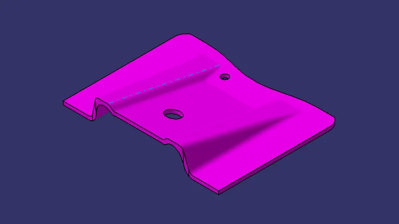
- FRONT VIEW :

- LH SIDE VIEW :

- TOP VIEW :
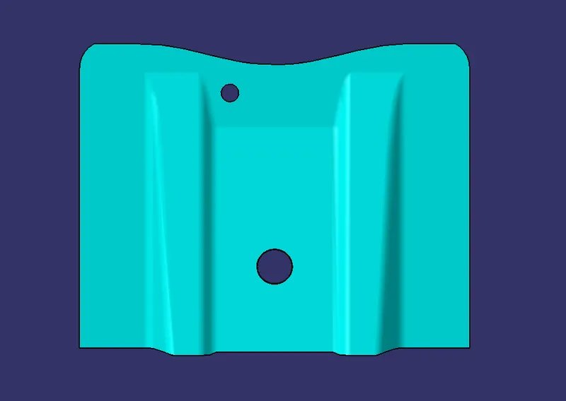
CONCLUSION :
Hence created the Base Bracket Plastic component through the given Class-A surface. To begin with, the tooling axis for the given Class-A Surface should be created meeting the requirements of the draft angle and at the end perform the Draft analysis on the model.
Solid oart with Thickness of Plastic Part - 2.5 mm.