Week 8 - Challenge 1 - Base Bracket Design
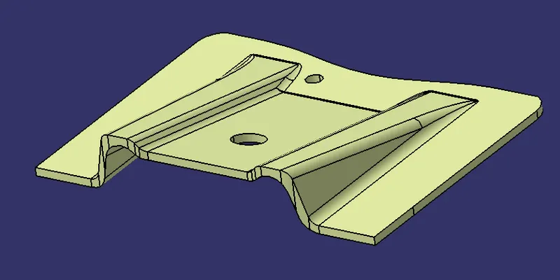
AIM: Create the Base Bracket Plastic component through the given Class-A surface. To begin with, the tooling axis for the given Class A Surface should be created meeting the requirements of the draft angle and at the end perform the Draft analysis on the model.
REPORT ON DRAFT ANALYSIS:
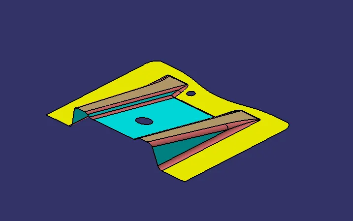
Given Class A Surface:
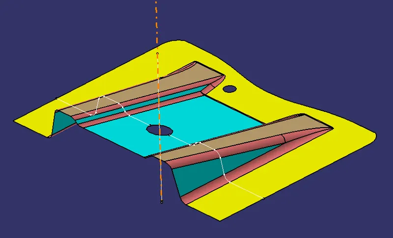
Creating a tooling axis in class A surface:
- The direction in which the mold opens and closes is the tooling axis.
- Check the connectivity of the surface and ensure there will be no gap between the surfaces and then define the tooling axis.
- While creating a tooling axis give the tooling axis on a flat-length surface or the surface which have a hole in it.
- Create a point on the surface where we are going to create the dummy tooling axis and using the line command create an axis. If there is a circle or flat length surface which is recommended.
Draft Analysis:
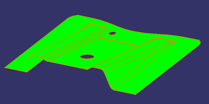
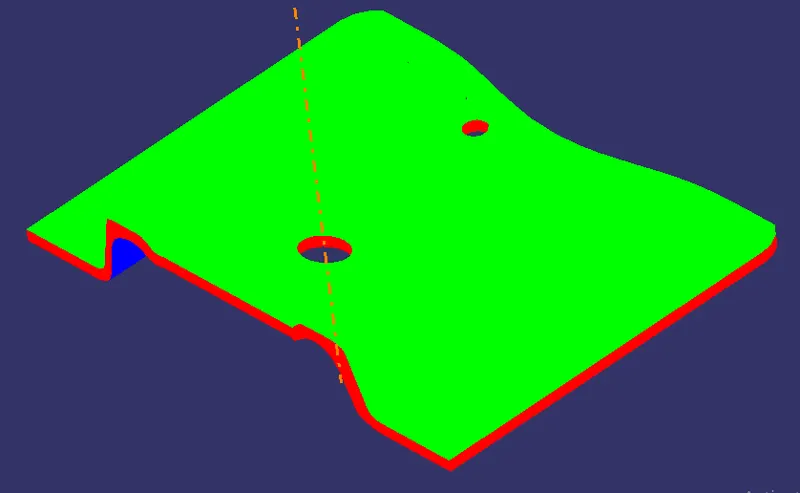
- The draft analysis technique is used to analyze whether our part model created in CAD is manufacturable based on the draft condition applied.
- Minimum draft angle is considered as 3 degrees.
- step 1= enter part in CATIA.
- step 2= Go to Material Mode.
- step 3= go for draft analysis.
- step 4= drag the axis bar to the tooling direction of the part.
- step 5= check for the draft and make a parting line as per the analysis.
Create a class B surface:
- Class B surfaces are the secondary surfaces in plastic component design.
- In this model Class B-Surface is extracted from the A-surface and it is offered at 2.5mm in a downward direction.
- To create the class B surface, I considered the entire surface has 3 parts 'Rib-1, Rib-2, and Base surface.
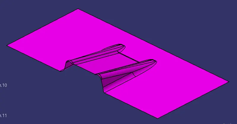
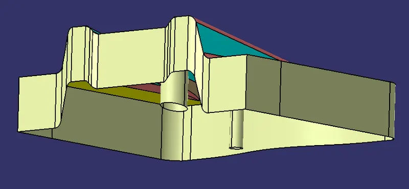
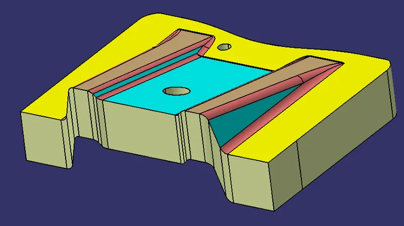
create a class C surface.
- Class C is often specified for interior surfaces not readily visible, surfaces that will be covered by another part when assembled, or surfaces that the Customer feels do not need to meet a high cosmetic finish.
- C-Surface connects the class A-Surface and B-Surface. It is created using the Sweep command. The boundary of the class A-Surface is swept along the tooling direction.
OUTPUTS:
Tooling Axis:
Class A Draft:
Class B:
Class C:
Final Closed surface:
Solid Part:
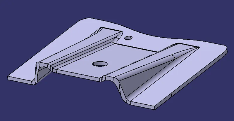
Solid Part Draft Analysis:
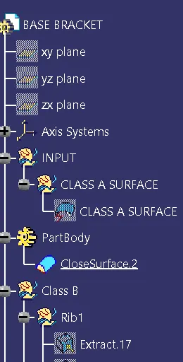
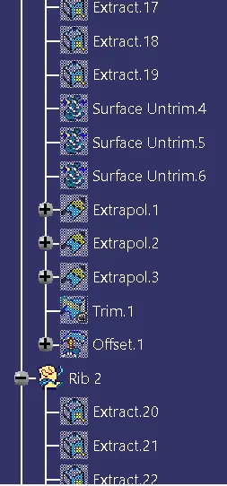
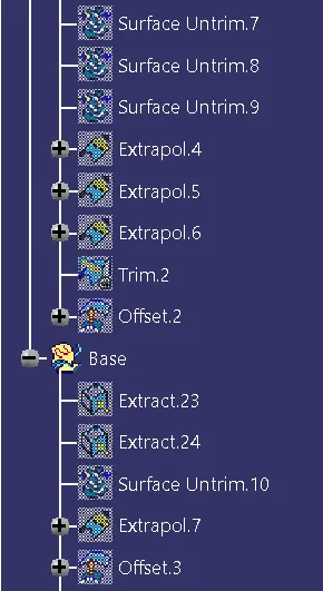
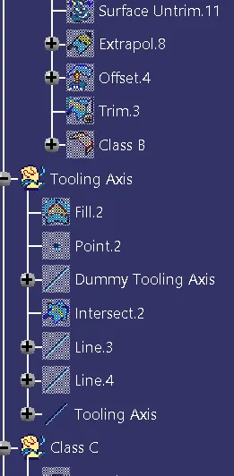
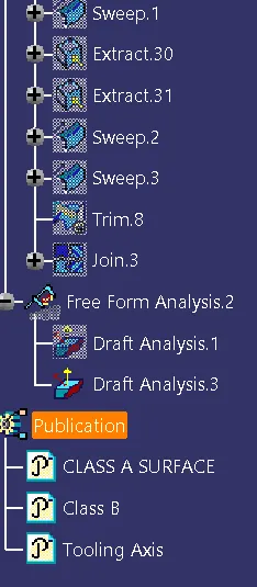
Tree: