Week 8 - BlockMesh Drill down challenge
AIM:
The Scope of this project is to simulate and study the blockmesh Drill down flow through backward facing step.
Mesh specification
- In this challange CFD Simulation will be performed by using OpenFoam.
- IcoFoam is a Solver which Solves the incompressible navier stokes equation for a flow consideration
We are assuming
- Number of cells along the x direction (longer dimension) = 50
- Number of cells along the y direction = 10
- Inlet Velocity = 2 m/s
- Study the velocity magnitude profile changes as a function of mesh grading factors (f = 0.2,0.6 & 0.8).
- Measure the velocity profile at 0.085 m from the inlet of the geometry
- Plot must be a line plot
- Compare velocity magnitude contours near the step region for the above mentioned grading factors.
INTRODUCTION:
The block Diagram looks in isometric view & 2-Dimensional View
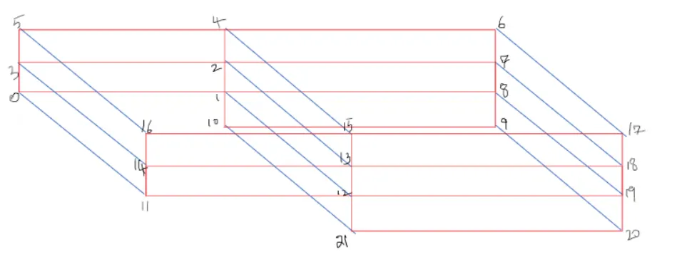
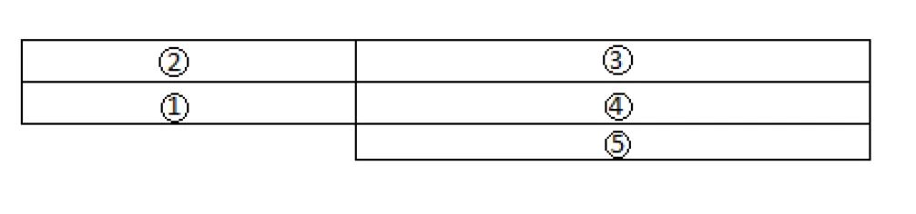
- In above Diagram view there are 5 blocks are used for this project.
- Aready mentioned the number of cells in the X-direction is 50 and in the Y-direction is 10 and Z-direction is 1.
SIMPLE GRADING FACTOR:
The Formula for finding Simple grading factor
f = Size of the end cell / Size of the start cell
SYSTEM FOLDER:
The function of this folder it controls numerical scheme and solution Procedure.
CONSTANT FOLDER:
- The function of this folder it handles the Meshing and physical properties which constant in the solution procedure.
- So that why its located in constant folder.
- It contains several properties like polymesh, points, cells, faces & boundary
TIME DIRECTORIES:
- The function of this folder it handles the solution at each and every instant of time.
- With out this three folders we cant run the simulation of any solvers in openfoam.
MAIN PROGRAM:
- The BlockMesh Dict file located in system folder wrt to that edit the file for problem geomentry and aslo update the boundary conditions Simultaneously.
- we have to edit code for grading Factor f=0.2 is given below
/*--------------------------------*- C++ -*----------------------------------*\
  =========                 |
  \\      /  F ield         | OpenFOAM: The Open Source CFD Toolbox
   \\    /   O peration     | Website:  https://openfoam.org
    \\  /    A nd           | Version:  6
     \\/     M anipulation  |
\*---------------------------------------------------------------------------*/
FoamFile
{
    version     2.0;
    format      ascii;
    class       dictionary;
    object      blockMeshDict;
}
// * * * * * * * * * * * * * * * * * * * * * * * * * * * * * * * * * * * * * //

convertToMeters 0.01;

vertices
(
    (0 0 0)        //Point 0
    (8 0 0)        //Point 1
    (8 0.5 0)      //Point 2
    (0 0.5 0)      //Point 3
    (8 1 0)        //Point 4
    (0 1 0)        //Point 5
    (20 1 0)       //Point 6
    (20 0.5 0)     //Point 7
    (20 0 0)       //Point 8
    (20 -1 0)      //Point 9
    (8 -1 0)       //Point 10
    (0 0 0.1)      //Point 11
    (8 0 0.1)      //Point 12
    (8 0.5 0.1)    //Point 13
    (0 0.5 0.1)    //Point 14
    (8 1 0.1)      //Point 15
    (0 1 0.1)      //Point 16
    (20 1 0.1)     //Point 17
    (20 0.5 0.1)   //Point 18
    (20 0 0.1)     //Point 19
    (20 -1 0.1)    //Point 20
    (8 -1 0.1)     //Point 21
);

blocks
(
    hex (0 1 2 3 11 12 13 14) (50 5 1) simpleGrading (0.2 2 1)
    hex (3 2 4 5 14 13 15 16) (50 5 1) simpleGrading (0.2 0.2 1)
    hex (1 8 7 2 12 19 18 13) (50 5 1) simpleGrading (2 2 1)
    hex (2 7 6 4 13 18 17 15) (50 5 1) simpleGrading (2 0.2 1)
    hex (10 9 8 1 21 20 19 12) (50 5 1) simpleGrading (2 2 1)
);

edges
(
);

boundary
(
    inlet
    {
        type wall;
        faces
        (
            (0 11 14 3)
            (3 14 16 5)
        );
    }
    outlet
    {
        type wall;
        faces
        (
            (9 8 19 20)
            (8 7 18 19)
            (7 6 17 18)
        );
    }

NoslipWall
    {
        type wall;
        faces
        (
            (5 16 15 4)
            (4 15 17 6)
            (0 1 12 11)
            (10 21 12 1)
            (10 9 20 21)
        );
    }
    frontAndBack
    {
        type empty;
        faces
        (
            (0 3 2 1)
            (3 5 4 2)
            (10 1 8 9)
            (1 2 7 8)
            (2 4 6 7)
            (11 12 13 14)
            (14 13 15 16)
            (21 20 19 12)
            (12 19 18 13)
            (13 18 17 15)
        );
    }
);

mergePatchPairs
(
);

// ************************************************************************* //
After the editing the blockmeshDict file blocks as per the given geomentry. we can see the geomentry with help of ParaFoam command.
PROGRAM FILE FOR PRESSURE BOUNDARY CONDITION:
- After editing the blockmeshDict file is next step to give and edit the boundary conditions as well for the geomentry.
- The location folder to edit the file of boundary condition for velocity and pressure it contains in 0 folder.
/*--------------------------------*- C++ -*----------------------------------*\
  =========                 |
  \\      /  F ield         | OpenFOAM: The Open Source CFD Toolbox
   \\    /   O peration     | Website:  https://openfoam.org
    \\  /    A nd           | Version:  6
     \\/     M anipulation  |
\*---------------------------------------------------------------------------*/
FoamFile
{
    version     2.0;
    format      ascii;
    class       volScalarField;
    object      p;
}
// * * * * * * * * * * * * * * * * * * * * * * * * * * * * * * * * * * * * * //

dimensions      [0 2 -2 0 0 0 0];

internalField   uniform 0;

boundaryField
{
    inlet
    {
        type            zeroGradient;
    }
    outlet
    {
        type            fixedValue;
        value           uniform 0 ;
    }

    NoslipWall
    {
        type            zeroGradient;
    }

    frontAndBack
    {
        type            empty;
    }
}

// ************************************************************************* //
PROGRAM FILE FOR VELOCITY BOUNDARY CONDITIONS:
/*--------------------------------*- C++ -*----------------------------------*\
  =========                 |
  \\      /  F ield         | OpenFOAM: The Open Source CFD Toolbox
   \\    /   O peration     | Website:  https://openfoam.org
    \\  /    A nd           | Version:  6
     \\/     M anipulation  |
\*---------------------------------------------------------------------------*/
FoamFile
{
    version     2.0;
    format      ascii;
    class       volVectorField;
    object      U;
}
// * * * * * * * * * * * * * * * * * * * * * * * * * * * * * * * * * * * * * //

dimensions      [0 1 -1 0 0 0 0];

internalField   uniform (0 0 0);

boundaryField
{
    inlet
    {
        type            fixedValue;
        value           uniform (0.02 0 0);
    }

    outlet
    {
        type            zeroGradient;
     }

    NoslipWall
    {
        type            noSlip;
    }

    frontAndBack
    {
        type            empty;
    }
}

// ************************************************************************* //
PROGRAM FILE FOR CONTROLDICT CONDITIONS:
/*--------------------------------*- C++ -*----------------------------------*\
  =========                 |
  \\      /  F ield         | OpenFOAM: The Open Source CFD Toolbox
   \\    /   O peration     | Website:  https://openfoam.org
    \\  /    A nd           | Version:  6
     \\/     M anipulation  |
\*---------------------------------------------------------------------------*/
FoamFile
{
    version     2.0;
    format      ascii;
    class       dictionary;
    location    "system";
    object      controlDict;
}
// * * * * * * * * * * * * * * * * * * * * * * * * * * * * * * * * * * * * * //

application     icoFoam;

startFrom       startTime;

startTime       0;

stopAt          endTime;

endTime         10;

deltaT          0.01;

writeControl    timeStep;

writeInterval   20;

purgeWrite      0;

writeFormat     ascii;

writePrecision  6;

writeCompression off;

timeFormat      general;

timePrecision   6;

runTimeModifiable true;


// ************************************************************************* //
- The pressure and velocity boundary conditions is in folder 0 and ControlDict is in system folder will remain constant for all the mesh grading factor which we are considering for this challange.
- Courant number is exceeds the maximum limit then we have to change the dt value for every mesh grading factor.
- The starting time is 0 and the end time is 10
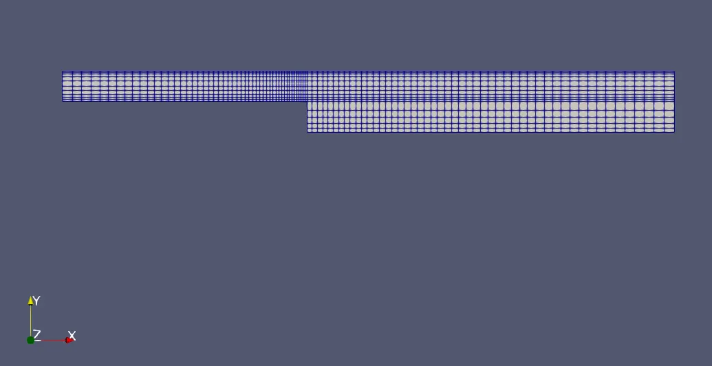
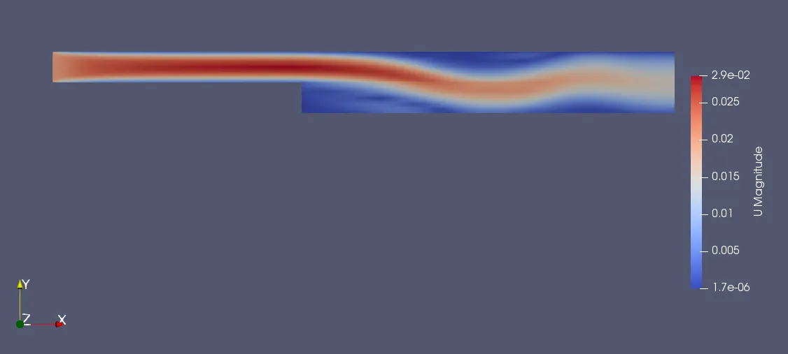
FOR SIMPLE MESHING GRADE FACTOR F = 0.2:
MESH BLOCK DIAGRAM:
VELOCITY VARIARTIONS DIAGRAM:
The main reason for introducing grading factor is to refine the mesh at the desired location for accurate solution
VELOCITY PROFILE:
The velocity profile at a distance of 0.085 m near the step from the inlet as shown below
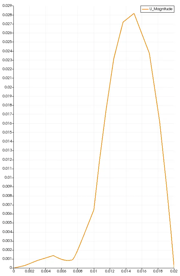
The Maximum Value of CFL number for last time step is found to be 0.452329
Then with help of Parafoam or Paraview by using line probe tool we can plot and analyse the velocity profile from line parameter point 1 to point 2 at x = 0.085 from Y = -0.01 to 0.01 , Z = 0.0005
BlOCKMESHDICT FILE FOR MESH GRADING FACTOR 0.6:
The BlockMesh Dict file located in system folder wrt to that edit the file for blocks. we have to edit code for grading Factor f=0.6 is given below
/*--------------------------------*- C++ -*----------------------------------*\
  =========                 |
  \\      /  F ield         | OpenFOAM: The Open Source CFD Toolbox
   \\    /   O peration     | Website:  https://openfoam.org
    \\  /    A nd           | Version:  6
     \\/     M anipulation  |
\*---------------------------------------------------------------------------*/
FoamFile
{
    version     2.0;
    format      ascii;
    class       dictionary;
    object      blockMeshDict;
}
// * * * * * * * * * * * * * * * * * * * * * * * * * * * * * * * * * * * * * //

convertToMeters 0.01;

vertices
(
    (0 0 0)      //Point 0
    (8 0 0)      //Point 1
    (8 0.5 0)    //Point 2
    (0 0.5 0)    //Point 3
    (8 1 0)      //Point 4
    (0 1 0)      //Point 5
    (20 1 0)     //Point 6
    (20 0.5 0)   //Point 7
    (20 0 0)     //Point 8
    (20 -1 0)    //Point 9
    (8 -1 0)     //Point 10
    (0 0 0.1)    //Point 11
    (8 0 0.1)    //Point 12
    (8 0.5 0.1)  //Point 13
    (0 0.5 0.1)  //Point 14
    (8 1 0.1)    //Point 15
    (0 1 0.1)    //Point 16
    (20 1 0.1)   //Point 17
    (20 0.5 0.1) //Point 18
    (20 0 0.1)   //Point 19
    (20 -1 0.1)  //Point 20
    (8 -1 0.1)   //Point 21
);

blocks
(
    hex (0 1 2 3 11 12 13 14) (50 5 1) simpleGrading (0.6 2 1)
    hex (3 2 4 5 14 13 15 16) (50 5 1) simpleGrading (0.6 0.6 1)
    hex (1 8 7 2 12 19 18 13) (50 5 1) simpleGrading (2 2 1)
    hex (2 7 6 4 13 18 17 15) (50 5 1) simpleGrading (2 0.6 1)
    hex (10 9 8 1 21 20 19 12) (50 5 1) simpleGrading (2 2 1)
);

edges
(
);

boundary
(
    inlet
    {
        type wall;
        faces
        (
            (0 11 14 3)
            (3 14 16 5)
        );
    }
    outlet
    {
        type wall;
        faces
        (
            (9 8 19 20)
            (8 7 18 19)
            (7 6 17 18)
        );
    }

NoslipWall
    {
        type wall;
        faces
        (
            (5 16 15 4)
            (4 15 17 6)
            (0 1 12 11)
            (10 21 12 1)
            (10 9 20 21)
        );
    }
    frontAndBack
    {
        type empty;
        faces
        (
            (0 3 2 1)
            (3 5 4 2)
            (10 1 8 9)
            (1 2 7 8)
            (2 4 6 7)
            (11 12 13 14)
            (14 13 15 16)
            (21 20 19 12)
            (12 19 18 13)
            (13 18 17 15)
        );
    }
);

mergePatchPairs
(
);

// ************************************************************************* //
MESH BLOCK DIAGRAM:
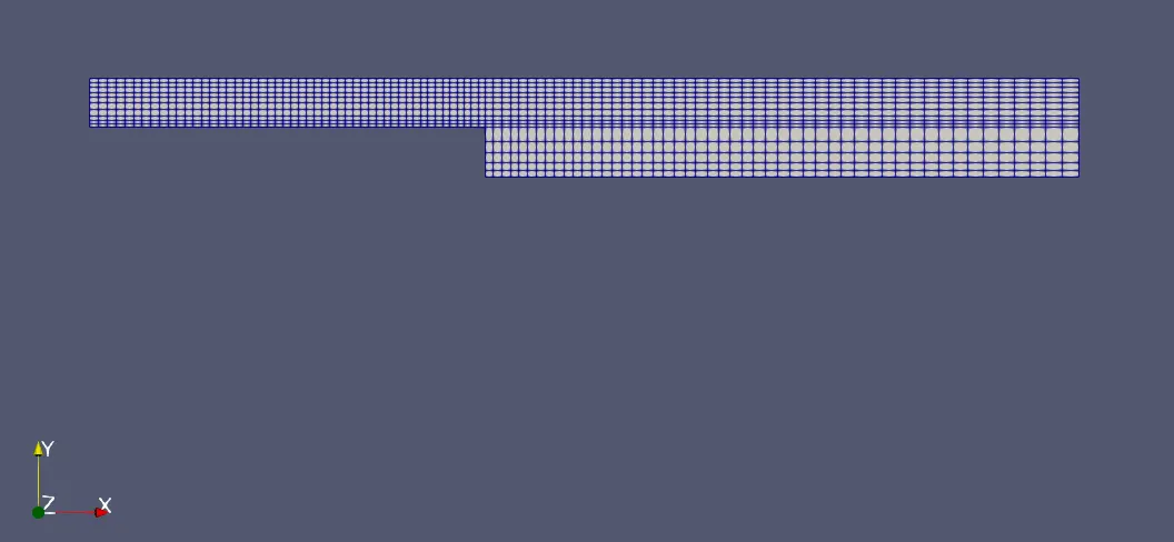
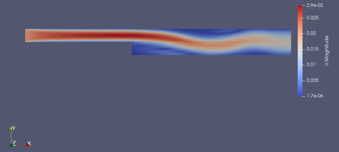
The Meshing and the velocity profile for grading scheme of 0.6 is shown below.
In the given boundary condition the gradingnear all wall is 0.6
VELOCITY VARIARTIONS DIAGRAM:
VELOCITY PROFILE:
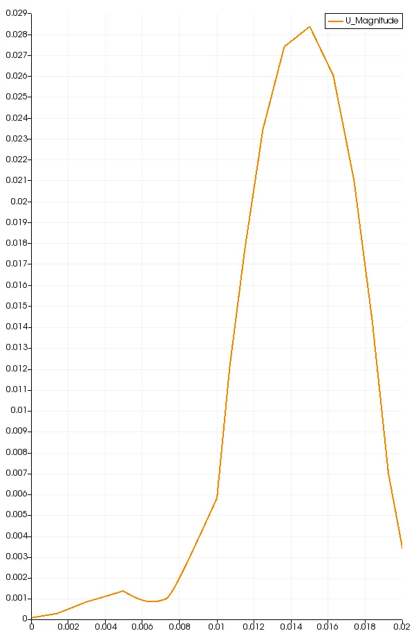
The Maximum Value of CFL number for last time step is found to be 0.240088
BlOCKMESHDICT FILE FOR MESH GRADING FACTOR 0.8:
- The BlockMesh Dict file located in system folder wrt to that edit the file for blocks.
- we have to edit code for grading Factor f=0.8 is given below
/*--------------------------------*- C++ -*----------------------------------*\
  =========                 |
  \\      /  F ield         | OpenFOAM: The Open Source CFD Toolbox
   \\    /   O peration     | Website:  https://openfoam.org
    \\  /    A nd           | Version:  6
     \\/     M anipulation  |
\*---------------------------------------------------------------------------*/
FoamFile
{
    version     2.0;
    format      ascii;
    class       dictionary;
    object      blockMeshDict;
}
// * * * * * * * * * * * * * * * * * * * * * * * * * * * * * * * * * * * * * //

convertToMeters 0.01;

vertices
(
    (0 0 0)        //Point 0
    (8 0 0)        //Point 1
    (8 0.5 0)      //Point 2
    (0 0.5 0)      //Point 3
    (8 1 0)        //Point 4
    (0 1 0)        //Point 5
    (20 1 0)       //Point 6
    (20 0.5 0)     //Point 7
    (20 0 0)       //Point 8
    (20 -1 0)      //Point 9
    (8 -1 0)       //Point 10
    (0 0 0.1)      //Point 11
    (8 0 0.1)      //Point 12
    (8 0.5 0.1)    //Point 13
    (0 0.5 0.1)    //Point 14
    (8 1 0.1)      //Point 15
    (0 1 0.1)      //Point 16
    (20 1 0.1)     //Point 17
    (20 0.5 0.1)   //Point 18
    (20 0 0.1)     //Point 19
    (20 -1 0.1)    //Point 20
    (8 -1 0.1)     //Point 21
);

blocks
(
    hex (0 1 2 3 11 12 13 14) (50 5 1) simpleGrading (0.8 2 1)
    hex (3 2 4 5 14 13 15 16) (50 5 1) simpleGrading (0.8 0.8 1)
    hex (1 8 7 2 12 19 18 13) (50 5 1) simpleGrading (2 2 1)
    hex (2 7 6 4 13 18 17 15) (50 5 1) simpleGrading (2 0.8 1)
    hex (10 9 8 1 21 20 19 12) (50 5 1) simpleGrading (2 2 1)
);

edges
(
);

boundary
(
    inlet
    {
        type wall;
        faces
        (
            (0 11 14 3)
            (3 14 16 5)
        );
    }
    outlet
    {
        type wall;
        faces
        (
            (9 8 19 20)
            (8 7 18 19)
            (7 6 17 18)
        );
    }

NoslipWall
    {
        type wall;
        faces
        (
            (5 16 15 4)
            (4 15 17 6)
            (0 1 12 11)
            (10 21 12 1)
            (10 9 20 21)
        );
    }
    frontAndBack
    {
        type empty;
        faces
        (
            (0 3 2 1)
            (3 5 4 2)
            (10 1 8 9)
            (1 2 7 8)
            (2 4 6 7)
            (11 12 13 14)
            (14 13 15 16)
            (21 20 19 12)
            (12 19 18 13)
            (13 18 17 15)
        );
    }
);

mergePatchPairs
(
);

// ************************************************************************* //
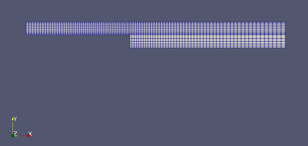
MESH BLOCK DIAGRAM:
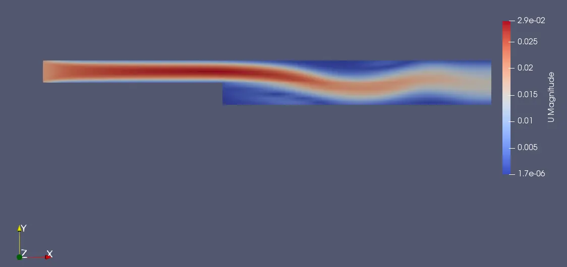
- The Meshing and the velocity profile for grading scheme of 0.8 is shown below.
- In the given boundary condition the gradingnear all wall is 0.8
VELOCITY VARIARTIONS DIAGRAM:
VELOCITY PROFILE:
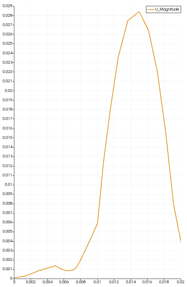
The Maximum Value of CFL number for last time step is found to be 0.206961
RESULT
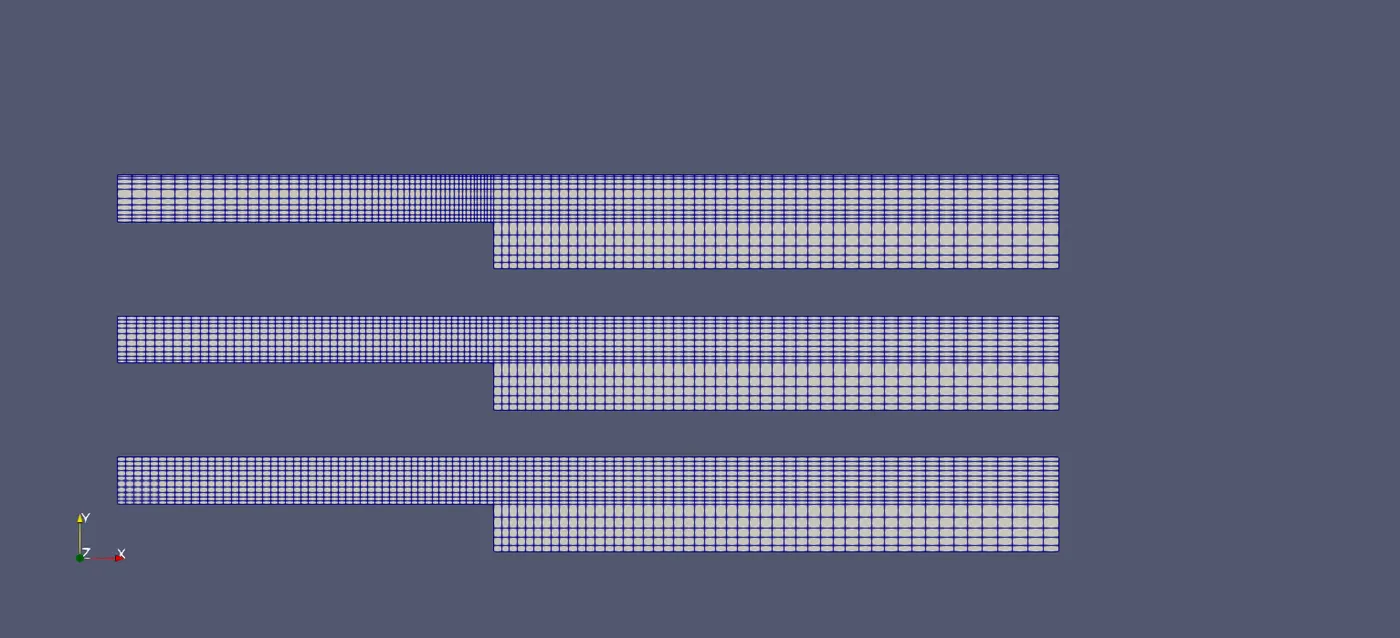
GRADING FACTOR F = 0.2,0.6 & 0.8 MESH BLOCK DIAGRAM:
VELOCITY VARIARTIONS FOR GRADING FACTOR F = 0.2,0.6 & 0.8 DIAGRAM:
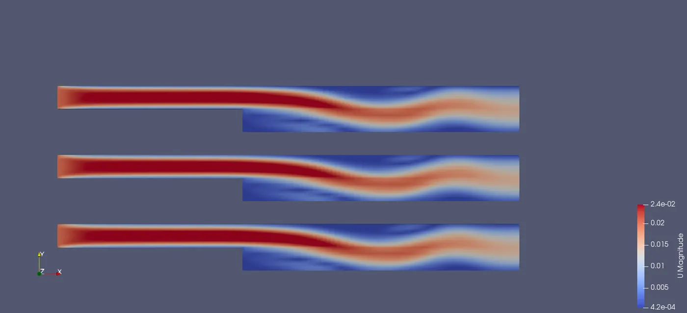
- We can observe the above mesh and velocity diagram for all the grading factors which we use in this challange.
- As we reducing the grading factor f = 0.2 the mesh becomes more finer and will get more accurate result as compared to grading factor 0.6 & 0.8.
CONCLUSION:
- From the above results there is no change in simulation but we can conclude that for mesh grading factor 0.2 obtaining a good results as compared to other mesh grading factor(0.6,0.8).
- In my case CFL number increases as the grading factor decreases.
- As the Mesher size is lower mesh will be finer and will get accurate output.