BlockMesh Drill down challenge
Objective:
To study the icoFOAM solver in order to simulate the flow through a backward-facing step.Also to create different meshes and compare the results obtained from them.
Given Data:
Mesh Specification:
- The number of cells along the direction of flow=200.
- The number of cells along the y-direction for each block=10.
- Inlet velocity is 1m/sec.
- Mesh Grading factor at the walls should be 0.2,0.5,0.8.
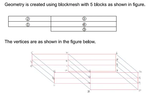
Step by step procedure for simulation:
- Firstly in Linux OS open “Terminal”.
- Type ‘tut’, on typing this will direct to the inbuilt tutorial files in openFOAM software. Nowto view the list of tutorials type ‘Is’.
- Once the list opens, we can see mulitple directories displayed. To select type ‘cd imcompressible/’. As above to go into the list type ‘Is’. Then it directs to the particular directory.
- As per the given data we need to solve the flow using the icoFOAM solver to simulate the flow through a backward-facing step. So type ‘cd icoFOAM/’. Go to the list and select cavity i.e. ‘cd cavity/’.
- Once we direct to the cavity folder it shows muliple files, here there is a file called ‘cavity’, this should be copied and paste the file to the ‘run folder’ by using the command ‘cp –r cavity $FOAM-RUN/(folder name where you saved the cavity in run folder without ‘/’)’.
- Now go back to the cavity folder that we have saved in run folder.type ‘IS’ to see the list in cavity. Go to ‘system’,to see the list type ‘Is’. It shows multiple files like blockMeshDict, fvschemes, fvsolutions.
- As we copied this form the tutorial they contain user defined values. So now, as per our geometry and the given data it could be modified carefully by typing ‘nano’ before the particular file which we are changing i.e. nano blockMeshDict.
- Here from the above files blockMeshDict –helps to give a perfect geometry,controlDict-helps to give the limits w.r.to time i.e.start time, endtime and the deltaT. the delta T value should be less than 1 as we know that the courant number should be less than 1.
- Again come back to the cavity file by using ‘cd .. ‘ command. From the list we need to select ‘0’’. Here ‘0’ represents the intial conditions of the problem.changes should be made as per cour calculations in velocity(U) and pressure(p) files respectively.
- After changing the data in the files it is manditory to save the file so as to overwrite the previous values.
- Go back to the cavity directory in run, by typing ‘blockMesh’. By giving this command it structures the mesh and internal calculations are done for a perfect meshing. After the end of running theblockMesh, now check for the errorsin the mesh by using ‘checkMesh’ command.
- Hence if there are no errors after checking the mesh we can say that it is atable.
- Now use ‘icoFoam’ command to run the simulation completely, this is because we used icoFoam as the solver for this problem. Wait untill it reaches the last time step. Check if it has excuited for all the time steps so that simulation goes smoothly.
- After the end of the simulationtype ‘paraFoam’. The command paraFoam directs to the paraview software directly by displayin the geometry.
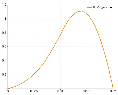
- Now find the velocity profile at 0.085m from the inlet of the geometry with a line plot.
- Now mesh grading factors of 0.2,0.5,0.8 are calculated for the geometry by using condition f=size of end cell/size of starting cell. These obtained plots are compared.
blockMeshDict:
/*--------------------------------*- C++ -*----------------------------------*
| =========                 |                                                 |
| \      /  F ield         | OpenFOAM: The Open Source CFD Toolbox           |
|  \    /   O peration     | Version:  v2006                                 |
|   \  /    A nd           | Website:  www.openfoam.com                      |
|    \/     M anipulation  |                                                 |
*---------------------------------------------------------------------------*/
FoamFile
{
    version     2.0;
    format      ascii;
    class       dictionary;
    object      blockMeshDict;
}
// * * * * * * * * * * * * * * * * * * * * * * * * * * * * * * * * * * * * * //

convertToMeters 0.01;

vertices
(
    (0 0 0)
    (8 0 0)
    (8 0.5 0)
    (0 0.5 0)
    (8 1 0)
    (0 1 0)
    (20 1 0)
    (20 0.5 0)
    (20 0 0)
    (20 -1 0)
    (8 -1 0)
    (0 0 0.1)
    (8 0 0.1)
    (8 0.5 0.1)
    (0 0.5 0.1)
    (8 1 0.1)
    (0 1 0.1)
    (20 1 0.1)
    (20 0.5 0.1)
    (20 0 0.1)
    (20 -1 0.1)
    (8 -1 0.1)
);

blocks
(
    hex (0 1 2 3 11 12 13 14) (200 10 1) simpleGrading (1 1 1)
    hex (3 2 4 5 14 13 15 16) (200 10 1) simpleGrading (1 1 1)
    hex (2 7 6 4 13 18 17 15) (200 10 1) simpleGrading (1 1 1)
    hex (1 8 7 2 12 19 18 13) (200 10 1) simpleGrading (1 1 1)
    hex (10 9 8 1 21 20 19 12) (200 10 1) simpleGrading (1 1 1)
);

edges
(
);

boundary
(
    inlet
    {
        type patch;
        faces
        (
            (0 11 14 3)
            (3 14 16 5)
        );
    }
    outlet
    {
        type patch;
        faces
        (
            (9 8 19 20)
            (8 7 18 19)
            (7 6 17 18)
        );
    }
    frontAndBack
    {
        type empty;
        faces
        (
            (0 3 2 1)
            (3 5 4 2)
            (10 1 8 9)
            (1 2 7 8)
            (2 4 6 7)
            (11 12 13 14)
            (14 13 15 16)
            (21 20 19 12)
            (12 19 18 13)
            (13 18 17 15)
        );
    }
Nospliwalls
{
type wall;
faces
   (
(15 16 15 4)
(4 15 17 6)
(0 1 12 11)
(10 21 12 1)
(10 9 20 21)
);
}
);
mergePatchPairs
(
);

// ************************************************************************* //
controlDict
/*--------------------------------*- C++ -*----------------------------------*
| =========                 |                                                 |
| \      /  F ield         | OpenFOAM: The Open Source CFD Toolbox           |
|  \    /   O peration     | Version:  v2006                                 |
|   \  /    A nd           | Website:  www.openfoam.com                      |
|    \/     M anipulation  |                                                 |
*---------------------------------------------------------------------------*/
FoamFile
{
    version     2.0;
    format      ascii;
    class       dictionary;
    location    "system";
    object      controlDict;
}
// * * * * * * * * * * * * * * * * * * * * * * * * * * * * * * * * * * * * * //

application     icoFoam;

startFrom       startTime;

startTime       0;

stopAt          endTime;

endTime         0.5;

deltaT          0.00001;

writeControl    timeStep;

writeInterval   20;

purgeWrite      0;

writeFormat     ascii;

writePrecision  6;

writeCompression off;

timeFormat      general;

timePrecision   6;

runTimeModifiable true;


// ************************************************************************* //
Pressure Boundary Conditions
  GNU nano 4.8                                                                                                          p                                                                                                                    /*--------------------------------*- C++ -*----------------------------------*
| =========                 |                                                 |
| \      /  F ield         | OpenFOAM: The Open Source CFD Toolbox           |
|  \    /   O peration     | Version:  v2006                                 |
|   \  /    A nd           | Website:  www.openfoam.com                      |
|    \/     M anipulation  |                                                 |
*---------------------------------------------------------------------------*/
FoamFile
{
    version     2.0;
    format      ascii;
    class       volScalarField;
    object      p;
}
// * * * * * * * * * * * * * * * * * * * * * * * * * * * * * * * * * * * * * //

dimensions      [0 2 -2 0 0 0 0];

internalField   uniform 0;

boundaryField
{
    inlet
    {
        type            zeroGradient;
    }

    outlet
    {
        type            fixedValue;
        value           uniform 0;
    }
    Noslipwalls
    {
        type            zeroGradient;
    }
    frontAndBack
    {
        type            empty;
    }
}

// ************************************************************************* //
Velocity Boundary Conditions
  GNU nano 4.8                                                                                                          U                                                                                                                    /*--------------------------------*- C++ -*----------------------------------*
| =========                 |                                                 |
| \      /  F ield         | OpenFOAM: The Open Source CFD Toolbox           |
|  \    /   O peration     | Version:  v2006                                 |
|   \  /    A nd           | Website:  www.openfoam.com                      |
|    \/     M anipulation  |                                                 |
*---------------------------------------------------------------------------*/
FoamFile
{
    version     2.0;
    format      ascii;
    class       volVectorField;
    object      U;
}
// * * * * * * * * * * * * * * * * * * * * * * * * * * * * * * * * * * * * * //

dimensions      [0 1 -1 0 0 0 0];

internalField   uniform (0 0 0);

boundaryField
{
    inlet
    {
        type            fixedValue;
        value           uniform (1 0 0);
    }

    outlet
    {
        type            zeroGradient;
    }
    Noslipwalls
    {
        type            noSlip;
    frontAndBack
    {
        type            empty;
    }
}

// ************************************************************************* //
After running the icoFoam solver,
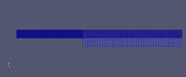
Mesh Block Diagram:
Case 1:
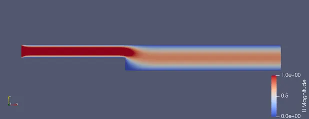
Velocity Plot:
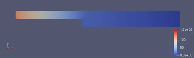
Pressure Plot:
Velocity Profile :
Case 2 :
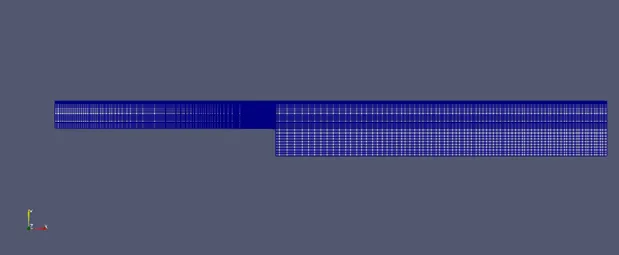
For this we kept the code same and a little bit changes are donei.e. in blocks what we changes in shown below remaing code has no changes.
blocks
(
hex (0 1 2 3 11 12 13 14) (200 10 1) simpleGrading (0.2 1.2 1)
hex (3 2 4 5 14 13 15 16) (200 10 1) simpleGrading (0.2 0.2 1)
hex (2 7 6 4 13 18 17 15) (200 10 1) simpleGrading (1.2 0.2 1)
hex (1 8 7 2 12 19 18 13) (200 10 1) simpleGrading (1.2 1.2 1)
hex (10 9 8 1 21 20 19 12) (200 10 1) simpleGrading (1.2 1.2 1)
);
Block Mesh Diagram:
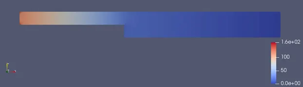
Pressure Plot:
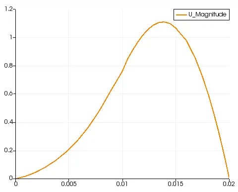
Velocity Profiles:
Case 3:
For this we kept the code same and a little bit changes are donei.e. in blocks what we changes in shown below remaing code has no changes.
blocks
(
hex (0 1 2 3 11 12 13 14) (200 10 1) simpleGrading (0.5 1.5 1)
hex (3 2 4 5 14 13 15 16) (200 10 1) simpleGrading (0.5 0.5 1)
hex (2 7 6 4 13 18 17 15) (200 10 1) simpleGrading (1.5 0.5 1)
hex (1 8 7 2 12 19 18 13) (200 10 1) simpleGrading (1.5 1.5 1)
hex (10 9 8 1 21 20 19 12) (200 10 1) simpleGrading (1.5 1.5 1)
);
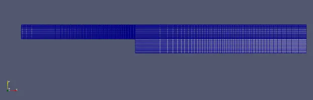
Mesh Block Diagram:
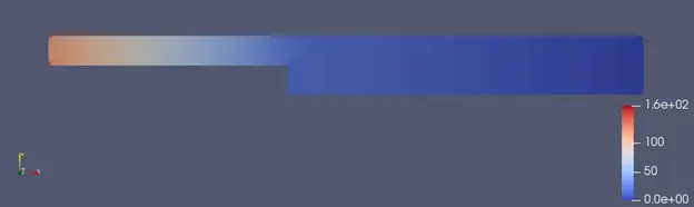
Pressure Plot:
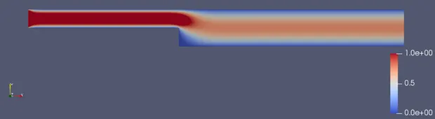
Velocity Plot:
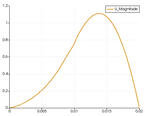
Velocity Profile:
Case 4:
For this we kept the code same and a little bit changes are done i.e in blocks what we changes is shownbelow remaining code has no changes.
blocks
(
hex (0 1 2 3 11 12 13 14) (200 10 1) simpleGrading (0.8 1.8 1)
hex (3 2 4 5 14 13 15 16) (200 10 1) simpleGrading (0.8 0.8 1)
hex (2 7 6 4 13 18 17 15) (200 10 1) simpleGrading (1.8 0.8 1)
hex (1 8 7 2 12 19 18 13) (200 10 1) simpleGrading (1.8 1.8 1)
hex (10 9 8 1 21 20 19 12) (200 10 1) simpleGrading (1.8 1.8 1)
);
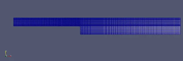
Mesh Block:
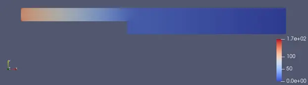
Pressure Plot:
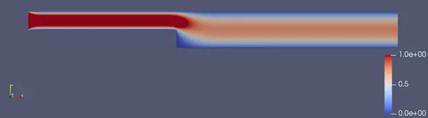
Velocity Plot :
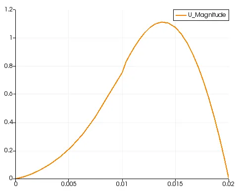
Velocity Profile:
|
Case No |
Mesh Grading Factor |
Maximum Velocity |
|
1 |
1 |
1.055 |
|
2 |
0.2 |
1.0583 |
|
3 |
0.5 |
1.0571 |
|
4 |
0.8 |
1.0546 |
Conclusion:
From the above plots, the change in velocity profile with mesh refinement is negligible.
From the table, there’s a small change in maximum velociy. As the grading factor decreases, it gives a smooth mesh resulting in better plots.