BlockMesh Drill down challenge
BlockMesh Drilldown challenge
Introduction:-
- OpenFOAM is an open-source CFD software used widely across different organizations. The basis of OpenFOAM runs on the core language of C++. With the help of preloaded solvers, the user can easily choose the required solver and method to solve the problem.
- BlockMesh is a utility command in OpenFOAM to create a meshed 3 dimensional part with grading and curved edges (if required). BlockMesh creates 1 or more 3D hexahedral blocks by decomposing the part and writes the data to points/cells, boundary, and face file.
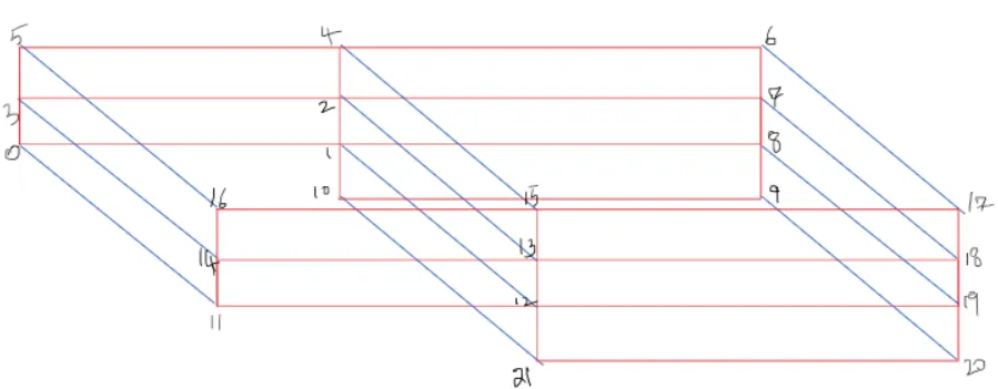
As seen in the above image, the part will be decomposed into 5 blocks and later a graded mesh will be used to mesh each part. The boundary type, edge type, and block will be defined using the blockMesh utility command. The part, also known as the backward-facing step can be seen in the below figure in a 3 Dimensional view divided into 5 blocks.
Objective:-
- To observe the change in the velocity magnitude profile as a function of the mesh grading factor for different mesh grading factors of 0.2,0.5 & 0.8.
- To measure the velocity profile at 0.085 m from the inlet of the geometry
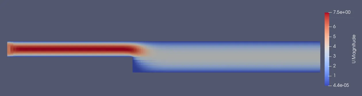
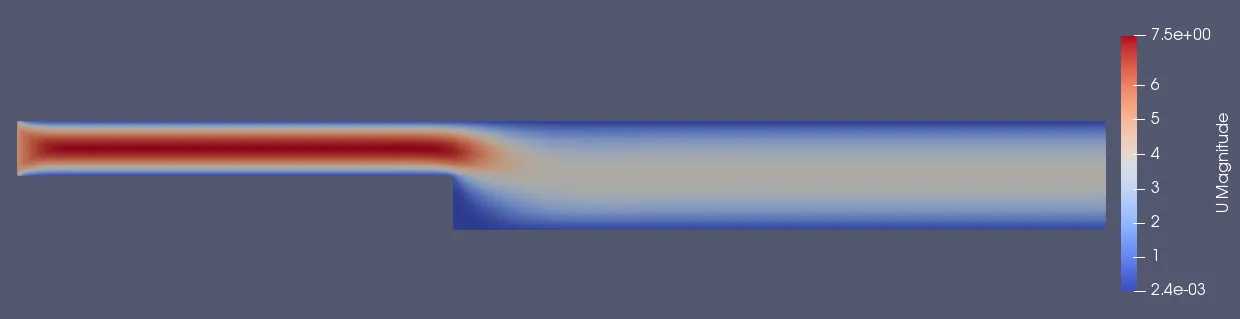
- To compare velocity magnitude contours near the step region for the above-mentioned grading factors.
Fluid properties and Solver type:-
- The fluid is considered to be incompressible & viscous. The flow is considered to have a low Reynolds number resulting in a laminar flow and unsteady.
- The most compatible solver in OpenFOAM for an incompressible, unsteady, laminar, and viscous flow is the icoFoam solver.
- icoFoam uses the PISO algorithm which stands for Pressure Implicit with Splitting of Operators to solve the continuity and momentum equation.
The equations are listed below.
Continuity: `grad.u = 0`
Momentum: `del/(delt)(u)+grad.(uoxu)-grad.(nugradu)=-gradp`
where,
u = Velocity (m/s)
p = kinematic pressure (m2/s2)
The PISO algorithm is a pressure-velocity calculator having a momentum predictor step and velocity corrector step to solve for the 4 unknown parameters which are velocity in x, y & z directions and the pressure.
Initial & Boundary Conditions:
blockMeshDict
The blockmeshdict file creates the vertices of the part as we define and then join the vertices to make edges of the blocks and later patches the blocks with each other in the blocks section and meshes the blocks with the defined number of cells and grading factor/type.
/*--------------------------------*- C++ -*----------------------------------*
  =========                 |
  \      /  F ield         | OpenFOAM: The Open Source CFD Toolbox
   \    /   O peration     | Website:  https://openfoam.org
    \  /    A nd           | Version:  7
     \/     M anipulation  |
*---------------------------------------------------------------------------*/
FoamFile
{
    version     2.0;
    format      ascii;
    class       dictionary;
    object      blockMeshDict;
}
// * * * * * * * * * * * * * * * * * * * * * * * * * * * * * * * * * * * * * //

convertToMeters 0.001;

vertices
(
    (0 0 0)                 /*0*/
    (80 0 0)                /*1*/
    (80 5 0)                /*2*/
    (0 5 0)                 /*3*/
    (80 10 0)               /*4*/
    (0 10 0)                /*5*/
    (200 10 0)              /*6*/
    (200 5 0)               /*7*/
    (200 0 0)               /*8*/
    (200 -10 0)             /*9*/
    (80 -10 0)              /*10*/
    (0 0 1)                 /*11*/
    (80 0 1)                /*12*/
    (80 5 1)                /*13*/
    (0 5 1)                 /*14*/
    (80 10 1)               /*15*/
    (0 10 1)                /*16*/
    (200 10 1)              /*17*/
    (200 5 1)               /*18*/
    (200 0 1)               /*19*/
    (200 -10 1)             /*20*/
    (80 -10 1)              /*21*/
);

blocks //mesh grading factor 0.2
(
    hex (0 1 2 3 11 12 13 14) (80 10 1) simpleGrading (0.2 5 1)
    hex (3 2 4 5 14 13 15 16) (80 10 1) simpleGrading (0.2 0.2 1)
    hex (2 7 6 4 13 18 17 15) (120 10 1) simpleGrading (5 0.2 1)
    hex (1 8 7 2 12 19 18 13) (120 10 1) simpleGrading (5 5 1)
    hex (10 9 8 1 21 20 19 12) (120 10 1) simpleGrading (5 5 1)

);

edges
(
);

boundary
(
    inlet
    {
        type patch;         //inletface
        faces
        (
            (0 11 14 3)
            (3 14 16 5)
        );
    }
    outlet
    {
        type patch;         //outletface
        faces
        (
            (9 8 19 20)
            (8 7 18 19)
            (7 6 17 18)
        );
    }

    fixedWalls
    {
        type wall;
        faces
        (
            (16 15 4 5)     //top
            (15 17 6 4)     //top
            (0 1 12 11)     //bottom
            (10 9 20 21)    //bottom
            (10 21 12 1)    //stepside
        );
    }

    frontandback
    {
        type empty;
        faces
        (
            (11 12 13 14)   //front
            (14 13 15 16)
            (13 18 17 15)
            (12 19 18 13)
            (21 20 19 12)
            (0 3 2 1)       //back
            (3 5 4 2)
            (2 4 6 7)
            (1 2 7 8)
            (10 1 8 9)
        );
    }
);

mergePatchPairs
(

);

// ************************************************************************* //
The mesh grading factor in this blockMesh file is 0.2. The blockMesh file for grading factors 0.5 & 0.8 will be almost the same except for the mesh grading part in the blocks section which will be changed for the respective grading factor are shown below.
Mesh grading factor of 0.5:
blocks //mesh grading factor 0.5
(
    hex (0 1 2 3 11 12 13 14) (80 10 1) simpleGrading (0.5 5 1)
    hex (3 2 4 5 14 13 15 16) (80 10 1) simpleGrading (0.5 0.5 1)
    hex (2 7 6 4 13 18 17 15) (120 10 1) simpleGrading (2 0.5 1)
    hex (1 8 7 2 12 19 18 13) (120 10 1) simpleGrading (2 2 1)
    hex (10 9 8 1 21 20 19 12) (120 10 1) simpleGrading (2 2 1)

);
Mesh grading factor of 0.8:
blocks //mesh grading factor 0.8
(
    hex (0 1 2 3 11 12 13 14) (80 10 1) simpleGrading (0.8 1.25 1)
    hex (3 2 4 5 14 13 15 16) (80 10 1) simpleGrading (0.8 0.8 1)
    hex (2 7 6 4 13 18 17 15) (120 10 1) simpleGrading (1.25 0.8 1)
    hex (1 8 7 2 12 19 18 13) (120 10 1) simpleGrading (1.25 1.25 1)
    hex (10 9 8 1 21 20 19 12) (120 10 1) simpleGrading (1.25 1.25 1)

);
controldict
The controldict file is a system file that defines/controls the type of application, start & end time, deltat, etc,. Therefore, the simulation is run for 0.01 seconds with 5E-5 as dt.
/*--------------------------------*- C++ -*----------------------------------*
  =========                 |
  \      /  F ield         | OpenFOAM: The Open Source CFD Toolbox
   \    /   O peration     | Website:  https://openfoam.org
    \  /    A nd           | Version:  7
     \/     M anipulation  |
*---------------------------------------------------------------------------*/
FoamFile
{
    version     2.0;
    format      ascii;
    class       dictionary;
    location    "system";
    object      controlDict;
}
// * * * * * * * * * * * * * * * * * * * * * * * * * * * * * * * * * * * * * //

application     icoFoam;

startFrom       startTime;

startTime       0;

stopAt          endTime;

endTime         0.01;

deltaT          0.00005;

writeControl    timeStep;

writeInterval   20;

purgeWrite      0;

writeFormat     ascii;

writePrecision  6;

writeCompression off;

timeFormat      general;

timePrecision   6;

runTimeModifiable true;


// ************************************************************************* //
Initial Pressure:
/*--------------------------------*- C++ -*----------------------------------*
  =========                 |
  \      /  F ield         | OpenFOAM: The Open Source CFD Toolbox
   \    /   O peration     | Website:  https://openfoam.org
    \  /    A nd           | Version:  7
     \/     M anipulation  |
*---------------------------------------------------------------------------*/
FoamFile
{
    version     2.0;
    format      ascii;
    class       volScalarField;
    object      p;
}
// * * * * * * * * * * * * * * * * * * * * * * * * * * * * * * * * * * * * * //

dimensions      [0 2 -2 0 0 0 0];

internalField   uniform 0;

boundaryField
{
    inlet
    {
        type            zeroGradient;
    }

    outlet
    {
        type            fixedValue;
        value           uniform 0;
    }

    fixedWalls
    {
        type            zeroGradient;
    }

    frontandback
    {
        type            empty;
    }

}

// ************************************************************************* //
Initial Velocity:
The initial velocity of the flow at the inlet face is considered to be 5m/s. The top and bottom walls are given a no-slip condition to catch the effect of the boundary layer concept.
/*--------------------------------*- C++ -*----------------------------------*
  =========                 |
  \      /  F ield         | OpenFOAM: The Open Source CFD Toolbox
   \    /   O peration     | Website:  https://openfoam.org
    \  /    A nd           | Version:  7
     \/     M anipulation  |
*---------------------------------------------------------------------------*/
FoamFile
{
    version     2.0;
    format      ascii;
    class       volVectorField;
    object      U;
}
// * * * * * * * * * * * * * * * * * * * * * * * * * * * * * * * * * * * * * //

dimensions      [0 1 -1 0 0 0 0];

internalField   uniform (0 0 0);

boundaryField
{
    inlet
    {
        type            fixedValue;
        value           uniform (5 0 0);
    }
    outlet
    {
        type            zeroGradient;
    }

    fixedWalls
    {
        type            noSlip;
    }

    frontAndBack
    {
        type            empty;
    }
}

// ************************************************************************* //
Meshing:-
Mesh grading factor:
- 0.2

- 0.5

- 0.8

From the above images, it can be observed that the mesh becomes more spatially equal when the grading factor is increased.
Post-Processing:
Pressure Contour:
Mesh grading factor of 0.2:
Mesh grading factor of 0.5:
Mesh grading factor of 0.8:
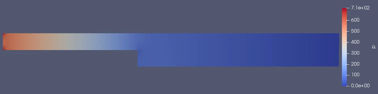
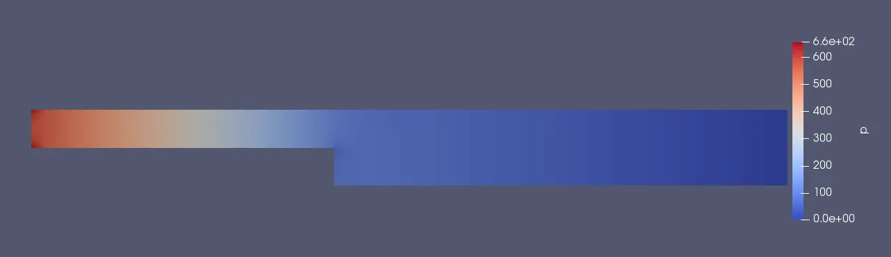
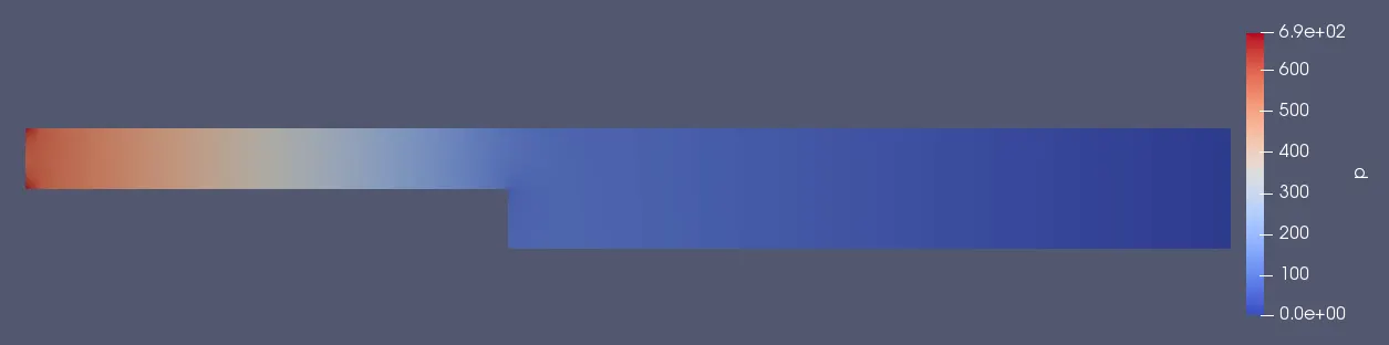
The kinematic pressure at the inlet face is about 660m2/s2, 690 m2/s2 and 710 m2/s2 for mesh grading factors of 0.2, 0.5 & 0.8 respectively. In all the cases above the kinematic pressure decreases along the path.
Velocity Contour:
Mesh grading factor of 0.2:
Mesh grading factor of 0.5:
Mesh grading factor of 0.8:
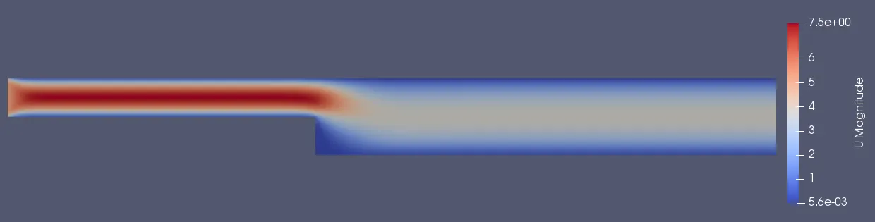
The magnitude of the velocity remains the same irrespective of the mesh grading factor which is observed from the above contours.
Velocity plot from Inlet face to 0.085m:

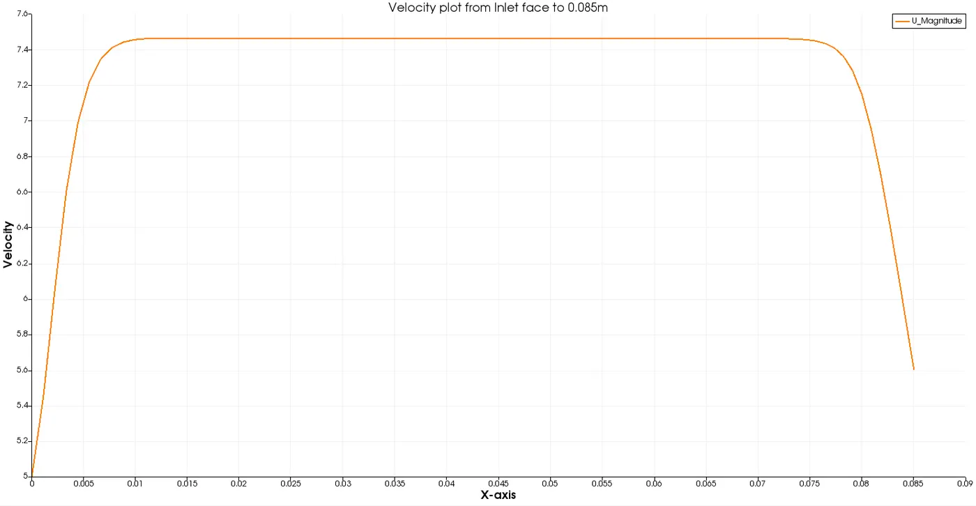
From both the velocity plot and contour, it can be observed that the velocity of the flow at the inlet face is about 7.5m/s at the center and continues to be 7.5m/s at the center of the flow along the path but is decreased at the walls due to the boundary layer effect. The velocity is later decreased due to the change in the geometry (step-side) which incurs the flow.
Velocity profile at 0.085m:

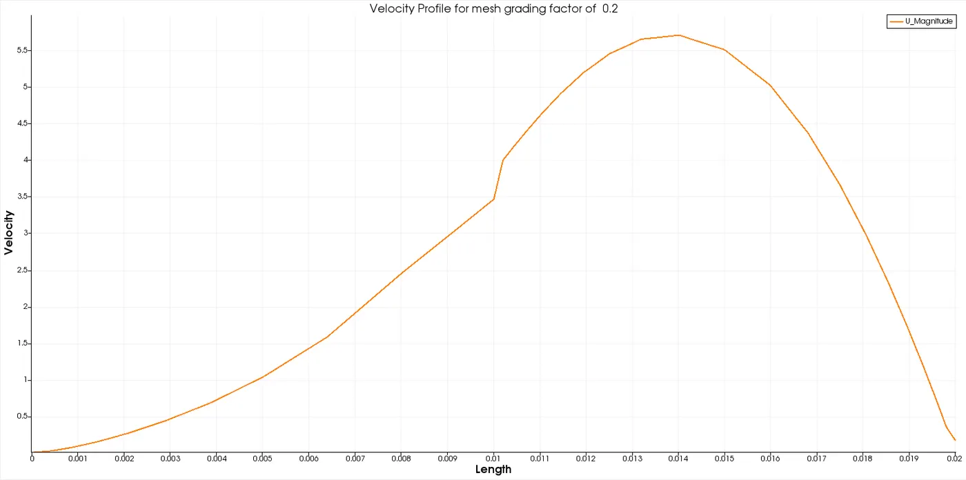
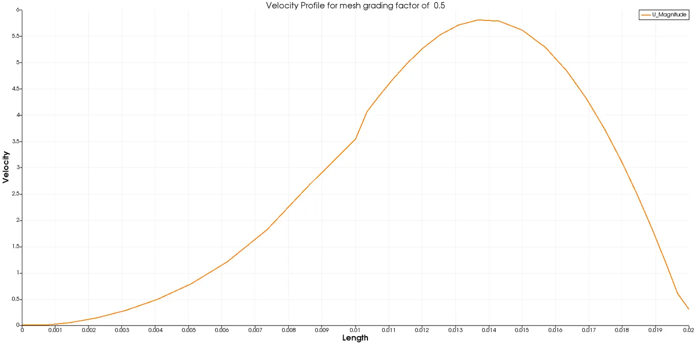
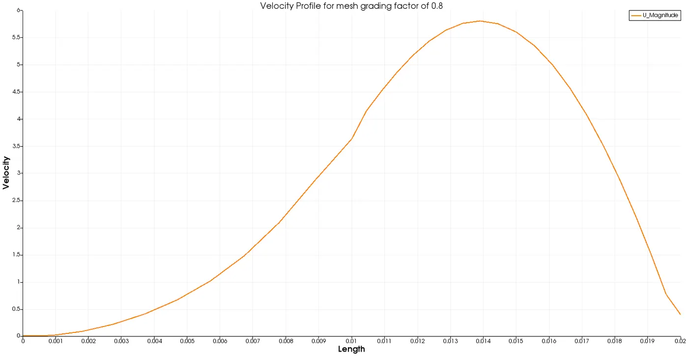
- It can be clearly observed that the velocity at the bottom wall will be zero due to the flow which is effected by the side-step and at the top wall will be almost zero due to the boundary layer concept. Although the maximum velocity can be obtained at 0.005m along the y-axis which is obtained in the above plot. Therefore, it can be concluded that the trend of the velocity profile is correct theoretically.
- It is also understood that the curve of the plot becomes slightly smoother when the mesh grading factor is increased.
- The velocity of the flow is maximum at the center of the block and minimum at the walls of the block due to the boundary layer effect, which can be also be seen in the velocity contours mentioned above.