3D Tetra Meshing
3D Tetra Meshing
Housing Model
Aim- To generate a 3D Tetra Mesh on the given components by using different methods.
Objective-
Generate 3D tetra mesh by using 3 methods called
- Conversion of a 2D element's into 3D elements.
- By doing Quick Tetra Mesh from the user interface panel.
- By doing Volume Tetra Mesh from 3d panel.
Intro to 3D Meshing and Some Terminologies -
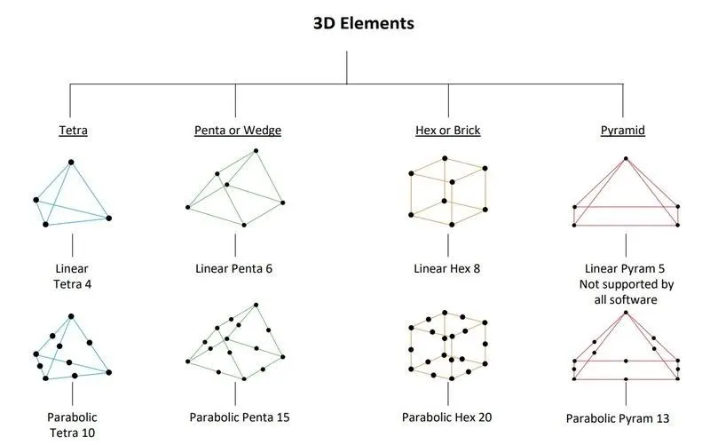
3D Element Types-
|
Figure 1-3D Element Types |
[Note: Penta and Pyramid elements are rarely used. But parabolic elements are the very very rare element's only used for 1 or 2 specific types of conditions.]
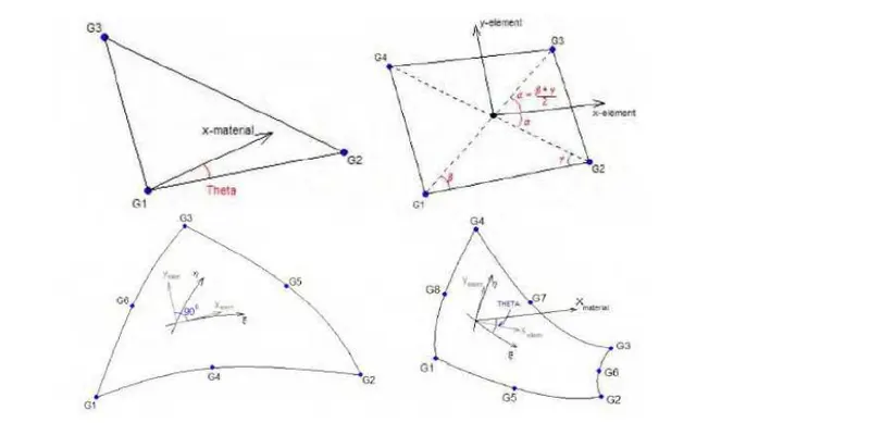
Shell Element-
|
Figure 1.1-Shell Element's |
Example of shell elements (CTRIA3, elements (CTRIA3, CQUAD4, CTRIA6, CTRIA6, CQUAD8)
- First Order 4 or 3 nodes.
- Second Order 6 or 8 nodes.
- DOFs 6 degrees of freedom per node.
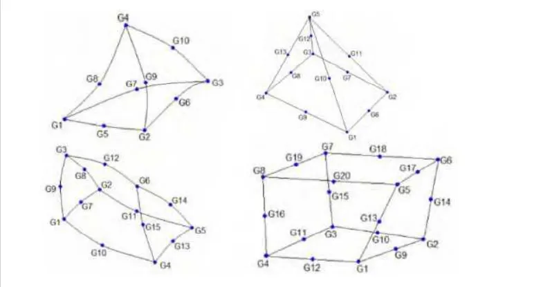
Solid Element-
|
Figure 1.2-Solid Element's |
Example of tetrahedron, pyramid, Penta and Hexa elements elements
- First Order 4, 5, 6, 8 nodes.
- Second Order 8, 12, 15, 20 nodes.
- DOFs 3 degrees of freedom per node.
Tetra Meshing Method's
There are two methods of tetra meshing:
1) Automatic mesh:
This approach is limited to simple geometries and the pre-requisite is an error-free CAD model. The user just has to select the volume and the software automatically carries out the meshing as per the specified element length, quality criteria, etc.
Advantage: Very quick, no meshing efforts.
Disadvantage: Results in a very high number of nodes and elements. There is no control over the mesh flow and the specific mesh pattern requirement (like bolted, welded joints, or contact surface simulation).
2) 2D (tria) to 3D (tetra):
This is the most commonly used method. Quad or tria meshing is carried out on all the outer surfaces of the geometry. During the tetra meshing the quads are automatically split into trias which then serve as the “basis” of the tetra elements.
Common Algorithms for Tria To Tetra Conversion -
- Advancing Front: This algorithm is very powerful and the most commonly used algorithm.
- Delaunay algorithm.
- Tria-quad mesh.
Procedure -
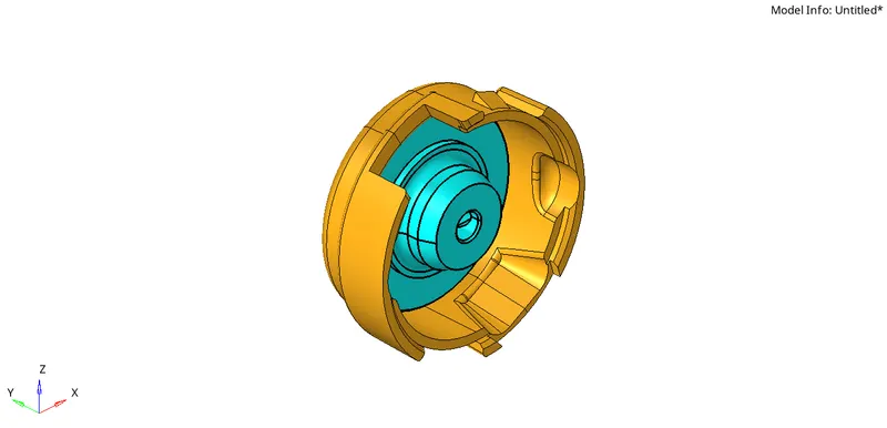
- Housing Model
Phase 1- Importing
- Hence we are importing a given CAD geometry into hypermesh.
b. There are file formats like IGES, STEP, Parasolid where we can import these file formats into any CAD, CAE Softwares.
c. But in hypermesh we can only import three file formats like
- IGES [Initial Graphics Exchange Specification].
- STEP [Standard for the Exchange of Product Model Data].
- Solidworks.
IGES, STEP, These two are standard file formats that are used most in industries. But nowadays in industries, they are also using Parasolid file format.
|
Figure 2-Imported Housing Model |
Phase 2- Examining
- Before working on the model. We have to check the geometry if there are any errors like
- Damaged Geometry.
- Free edges in unnecessary areas.
- Unnecessary points on the lines.
- Unnecessary Connections and connectivity errors.
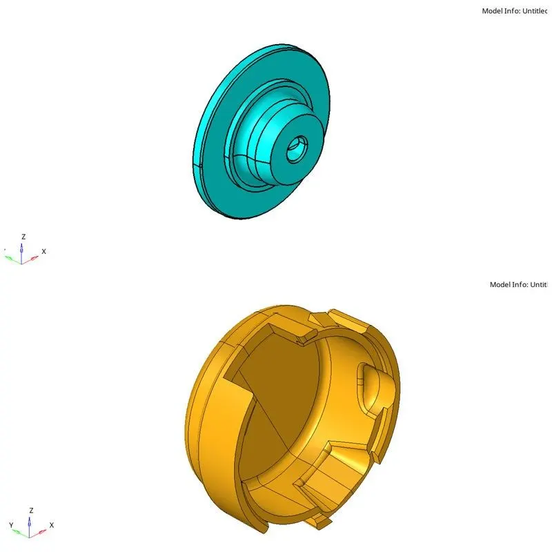
- By assessing the given three models. We can see the components in every model.
Housing Model
Two Component's
|
Figure 3-Housing Component's |
Phase 3 - Creating 2D Shell Element's on the Geometry
- For this model, I'm using the 2D tria to 3D tetra method.
- First, delete the solid if it exists in the component.
- With the surface geometry,automesh the component from the 2D panel.
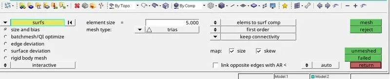
- While meshing the component, Change element size to 5, In the mesh type drop-down menu, switch to the trias and mesh the component.
- 2D Panel⇒⇒automesh⇒⇒surface⇒⇒displayed⇒⇒element size-5⇒⇒mesh type-trias⇒⇒mesh
|
Figure 4-Meshing Process |
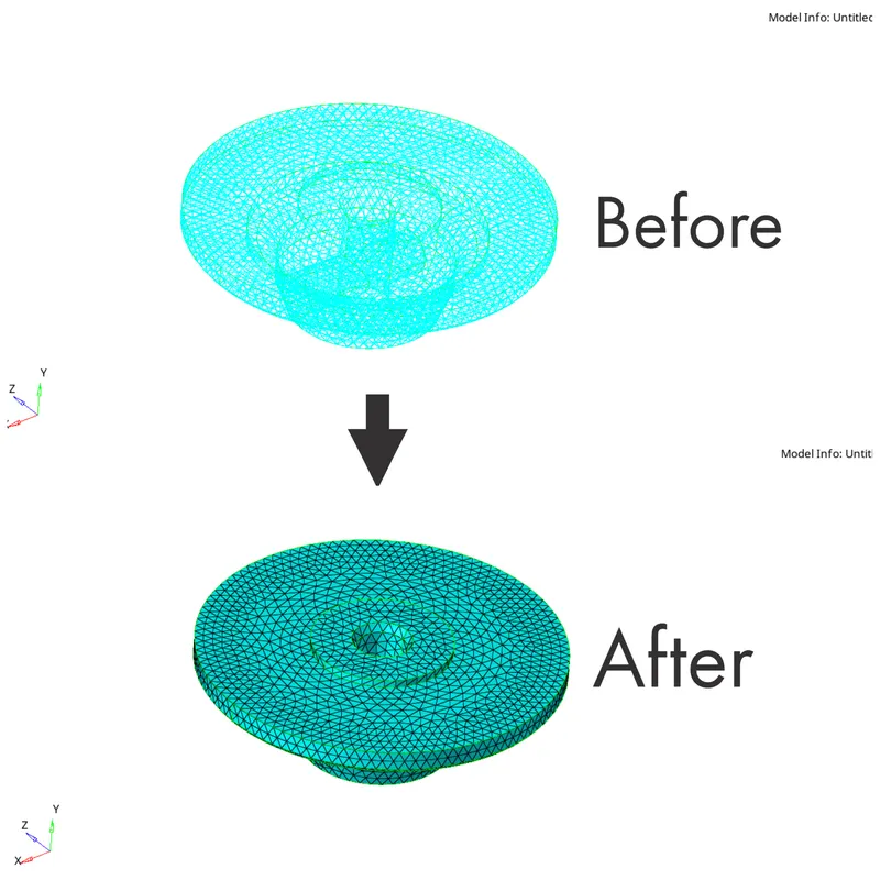
- After meshing the component, If it is in wireframe elements mode, Switch to the shaded elements mode.
|
Figure 5- Switching element mode |
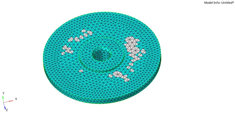
- Now I have made 2D Shell elements, Check for the element quality and eliminate the element's failing for min and max length.
- Here elements are not failing for min length.
- It is failing for max length. Try to eliminate them.
|
Figure 6-Element's failing for max length |
To check the element's failing for max length.
- Go to the Tool's⇒Check elements or (F10)⇒Max length⇒It will show elements failing.
To clear the element's failing for max length.
- Go to the Tool's⇒Check elements⇒Max length⇒Save failed.
- Tool's⇒Mask or (F5)⇒Elements⇒Right-click⇒Retrieve⇒Mask⇒Reverse⇒Mask adjacent.
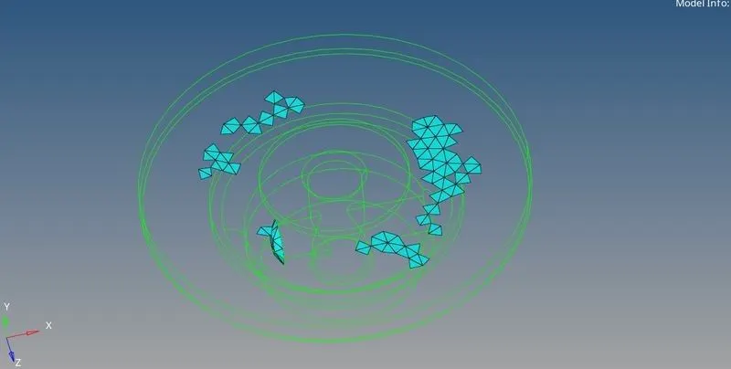
|
Figure 7-Failed Elements will be displayed like this |
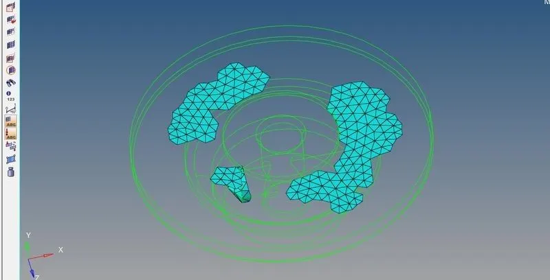
|
Figure 8-Make it unmask adjacent |
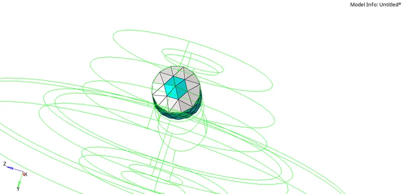
|
Figure 9-For this particular region, Element's will be failing for max length, Remesh that particular region with element size as 4, Before it was 5. Change it. So the element size will be applied for that particular region only. |
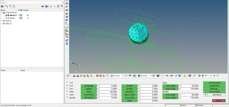
|
Figure 10-Now elements are not failing after remeshing with element size as 4. |
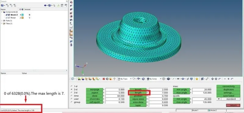
|
Figure 11-Ramesh |
3.1 Start Tetra Meshing
3D Panel⇒Tetramesh⇒Element's⇒Mesh.
Tetrameshing: Standard Tetrameshing
- Standard tetra meshing: 3D > tetra mesh panel > Tetra Mesh sub-panel
Process:
- Generate a surface mesh of shell elements
- Check quality and connectivity of the plate elements.
- Generate the tetrahedral mesh.
- Delete the original surface mesh.
- Edit if necessary to obtain good quality.
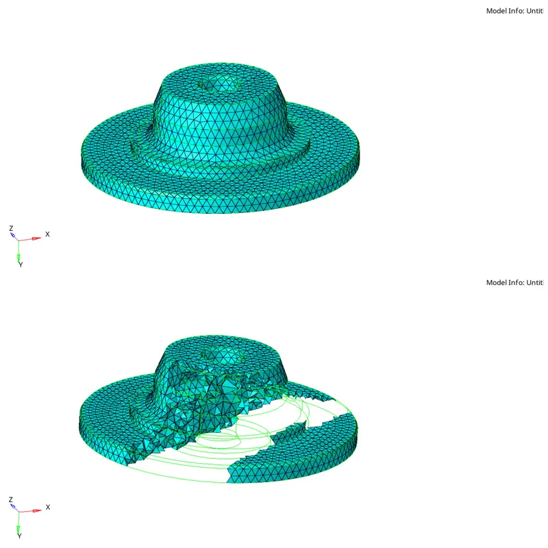
|
Figure 12-Tetramesh |
After Tetrameshing, Mask the elements in a particular region and see, whether the tetra elements are created as 3D(Solid).
3:2 Check whether the elements are failing for Tet Collapse
- In 2D Tetramesh, We will be checking whether elements are failing for only min and max length.
- In 3D Tetramesh, We will be checking whether elements are failing for the only tetcollapse.
3:3 Other Checks for Tetra Meshes
- Quality checks for 2D tria elements: Before converting trias to tetras, all the quality checks as discussed for shell elements should be applied.
- Free edges: Conversion from tria to tetra is possible only when there are no free edges.No free edges indicate the mesh is enclosing a volume.
What is Tet Collapse?
Tet Collapse can be calculated by measuring the distance of a node from the opposite face, then each of the four values will be divided by the Square root of the opposite face's area. The minimum of four resulting values is then normalized by dividing it by 1.24.
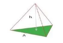
|
Figure 13-Tet Collapse |
Tetra elements whose collapse value falls below the value specified are highlighted when the tetra collapse function is selected. These elements remain highlighted until the Check Elems panel is exited.
Tetra collapse calculation: At each of the four nodes of the tetra, the distance from the node to the opposite side of the element is divided by the square root of the area of the opposite side. The minimum value found is normalized by dividing it by 1.24, and then reported. As the tetra collapses, this value approaches 0.0. For a perfect tetra, this value is 1.0.
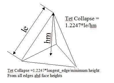
|
Figure 14-Tet Collapse Formula |
3:4 Tetra Remeshing to clear the element's failing for tetcollapse
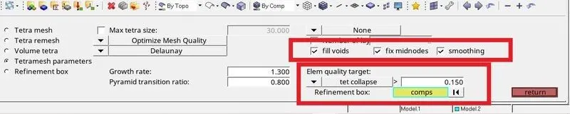
Before Tetra remeshing, Go to Tetramesh parameter's⇒Tick all CheckBoxes Fill Voids⇒Fix mid nodes⇒Smoothing to get better quality.
In the Tetramesh panel, In boundary faces drop-down menu change it to remeshable and mesh.
|
Figure 15-Tetramesh Parameter's |
Why ticking the checkbox of Fill Voids?
Mesh all volumes, if your geometry includes volumes inside of another volume. For example, if you had a sphere inside of a larger sphere, checking this option would cause the volume of the inner sphere as well as the volume between the two spheres to be meshed.
Why ticking the checkbox of Fix Midnodes?
In the case of 2nd order tetras, this option fixes the mid edge node of surface mesh while volume meshing.
Why ticking the checkbox of Smoothening?
Apply an extra stage of calculation to improve overall mesh quality. Additional smoothing and swapping steps will be performed and tetra elements will be split to achieve a smoother mesh transition. If tetra elements are used in the boundary layer those elements will be excluded from smoothing to maintain the original distribution.
|
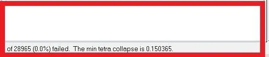
Figure 16-After Tetra Remeshing |
3:5 Manually clearing the element's failing for tetcollapse by using
- Distance Tool
- Translate Tool
After Tetramesh, Make sure to delete the 2D shell elements.
Phase 4
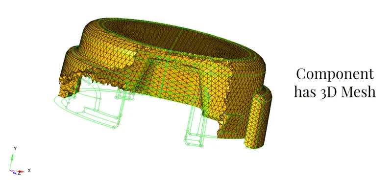
Similarly, as I did for the above component, Do the same thing for this component also.
|
Figure 17- 3D Tetramesh |
|
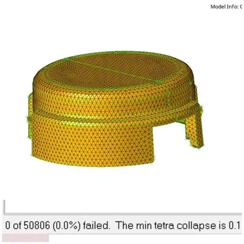
Figure 18-After tetraremeshing, no elements are failing for tetcollapse. |
Model-2
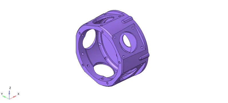
Only One Component
|
Figure 19-Model 2 |
For this component, Make a quick tetra mesh or Volume tetra mesh.
Quick Tetramesh
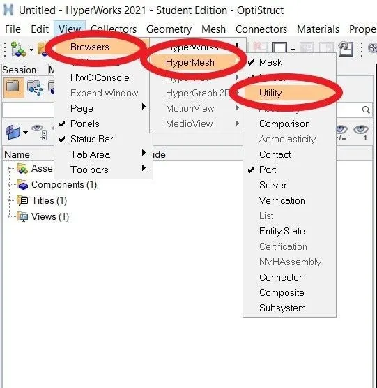
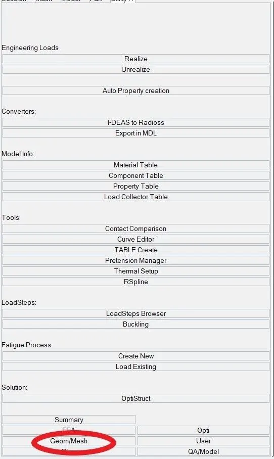
- Quick tetra mesh tool is accessed by going to View>Browsers>Hypermesh>Utility>Geom/Mesh>Quick tetra mesh.
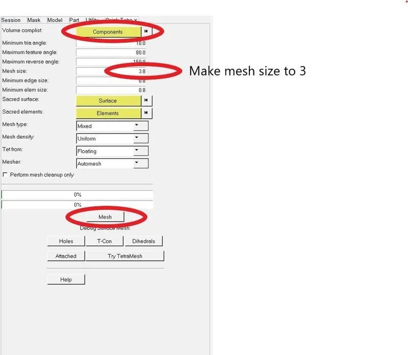
- In the Quick tetra mesh tool, the component & surfaces are selected, mesh size is set to 3 units, and mesh type is set to Trias only. After clicking on mesh, a new component will be generated with the tetra mesh.
- Geom/Mesh page of the Utility menu.
- Provides a quick method of generating a tetra mesh.
- Maintains specified minimum element quality criteria.
- The resulting tetra mesh may deviate from the geometry to maintain good element quality.
- Users can select “sacred elements” or “sacred surfaces” to force the tetra mesh to closely follow the original elements/surfaces.
- Click Help on the Quick Tetramesh panel for a description of the inputs.
|
Figure 20-Geometry |
|
Figure 21-Geometry/Mesh |
|
Figure 22-Quick Tetramesh Panel |

|
Figure 23-Switch to the elements and proceed |
|
Figure 24-Meshed |
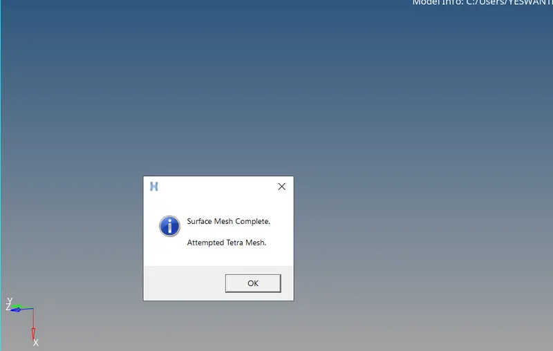
- Now the component has meshed with Quick Tetramesh Method.
- After meshing Quick Tet's component will be created individually.
- Now rename that Quick Tet's Component or Organize it to the Crank Casing Component.
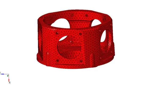
|
Figure 25-Quick Tetramesh |
- Make Sure to delete the 2D Shell Element's.
- Check for the element's failing for the Tetcollapse.
- Try to clear them using Tetraremesh.
- We can also try to clear them using Solid Mesh Optimization.
- If one or two elements are failing, We can clear them manually using Translate and Distance Tool.
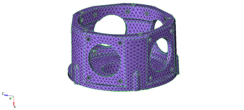
- Unmask Adjacent and tetraremesh the elements.
- Elements will be cleared.
|
Figure 26-Tetraremeshed Component |
Model-3
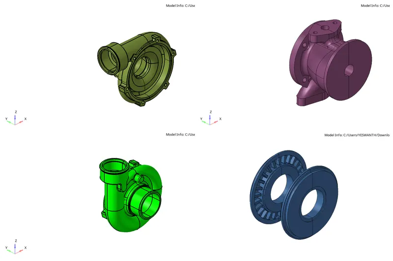
Four Component's-Two Casing, Central Hub, Hub
|
Figure 27-Model 3 Components |
- For this model, I'm using the Quick Tetramesh method as used for model 2.
- Follow the same steps as model 2.
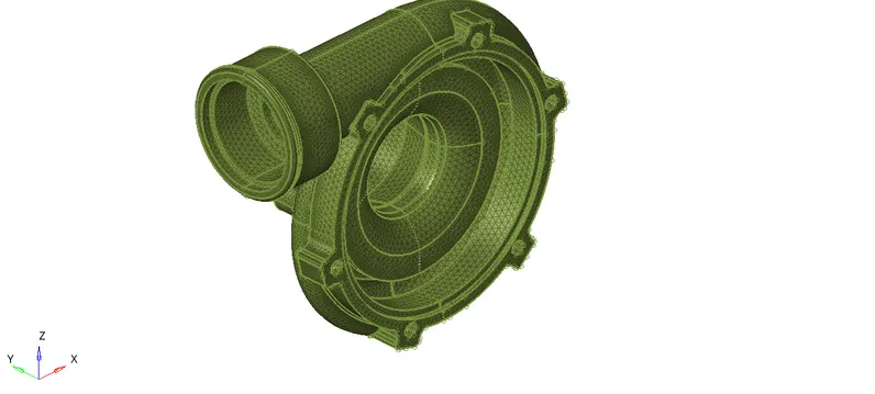
|
Figure 28-Casing 1 Tetramesh |
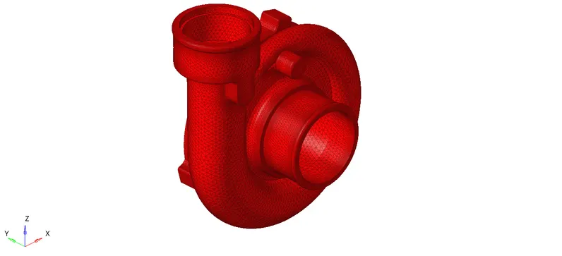
|
Figure 29-Casing 2 Tetramesh |
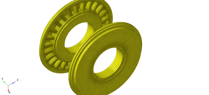
|
Figure 30-Side discs Tetramesh |
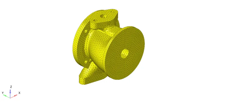
|
Figure 31-Central Hub Tetramesh |
Final CAD Model Image -
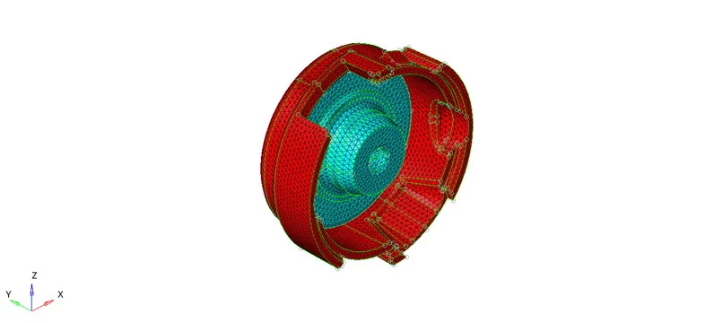
|
Figure 32-Model 1 |
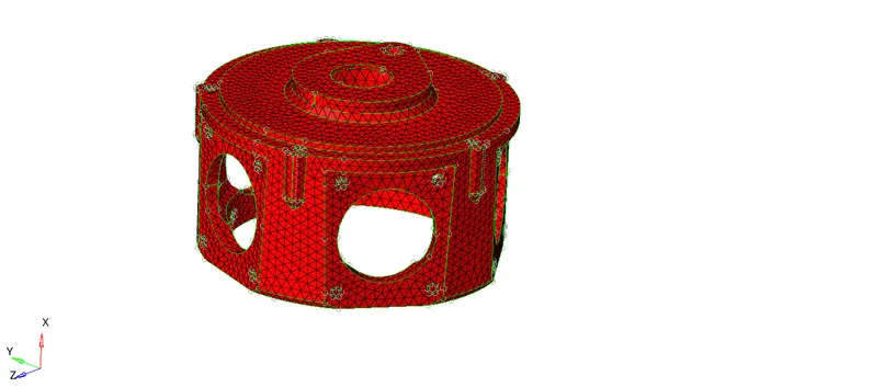
|
Figure 33-Model 2 |
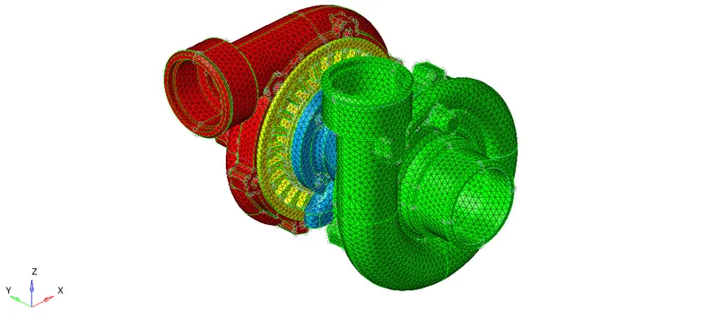
|
Figure 34-Model 3 |
Result -
- Hence TetraMesh Generation Method-2D to 3D Conversion for Housing component with the following quality criteria has been done.
- Hence TetraMesh Generation Method-Quick Tetra Mesh/ Volume Tetra Mesh for the given model with the following quality criteria has been done.
- Hence TetraMesh Generation Method-Quick Tetra Mesh/ Volume Tetra Mesh for the given assembly model with the following quality criteria has been done.
Conclusion and Learning Outcome -
- In this Week 8 Challenge, I came to know how to 3D mesh components properly without dents and kinks.
- Get to know how to 3D Mesh with different three methods and advantages of those methods.
- How to do Quick Tetramesh, Volume Tetramesh.
- How to do Solid Mesh Optimization.