Week 8:- 3D Finishing - Challenges 1
Q1. What do you understand about the 3D finish process?
A1.As indicated in the diagram below, the 3D finish is the process by which a design is totally finished and ready for final simulation and 2D details.The nominality of each unit and hole is examined when the design is being finalised to guarantee that all pieces can be simply installed. To ensure that the various pieces can be simply assembled, the concentricity and size of the holes should be examined. For different sorts of holes/parts, fasteners are implemented based on hole size and standard colour codes based on customer needs.
Standard hole colors are violet for a simple hole, yellow for a threaded hole, cream for a machined area, and blue for a dowel pin hole. After completing all of the preceding steps, the model is sent for simulation and 2D detailing.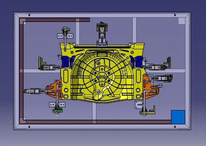
Q2. What are the points need to be taken care of while finishing the design?
A2.identify each and every part easily with unique identification.
- Nominality : All unit dimensions should be maintained nominal to facilitate easy assembly of the unit from a fixed edge.
- Hole concentricity & hole sizes: All parts are to be checked for hole concentricity and to be confirmed for easy assembly while finishing the parts.
- Machining area: The machining area in every part should be defined and the machining area should be highlighted by using standard color code.
- Gaps checking: Proper gap should be maintained between units to avoid the clash between the different units.
- Fasteners implementation: Fasteners should be implemented in all unit as per the requirement and load on the part.
Q3. What are rough locators & what is their use?
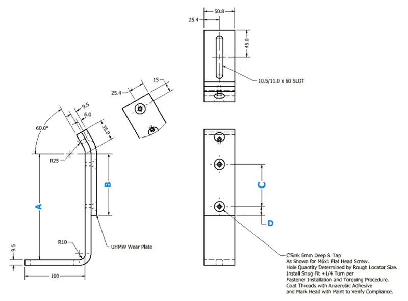
A3.A rough locator is a part that instructs the operator on where to place the car panel on the pins. A rough locator can be either a standard or a custom part. Rough locators are used in the automation process to help locate workpieces. The desired location where you want the workpiece to be when it is being worked on by a person, team, or robot is referred to as "locating."
- During the automation process, rough locators assist in the location of workpieces. When a person, team, or robot is working on a workpiece, the term "locating" refers to the desired placement of the workpiece.
The precision of the locating components has a direct impact on the end product's consistency and quality. This is why these aspects of your setup are so important.
It is also known as a fool-proofing technique. The rough locator prevents the part from being loaded in the incorrect location. The part can only be loaded in the appropriate direction and orientation since the rough locators are set based on the angle of the relevant panel.
Q4. What are the points you need to consider while designing a rough locator?
A4.The rough locator should be put along the edges of the automobile panel that it will be guiding.
With a minimum distance of 2-5 mm from the edge of the automobile part, the rough locator must be set at the same angle as the car part edge.
The panel should be guided in a pin arresting direction using the rough locator.
Before 10-15mm to the start of the pin engagement, use a rough locator to guide the panel.
The rough locator should have two places for mounting the simple adjustments.
The slots should face the car part directing direction.
Q5. What is the gun study process?
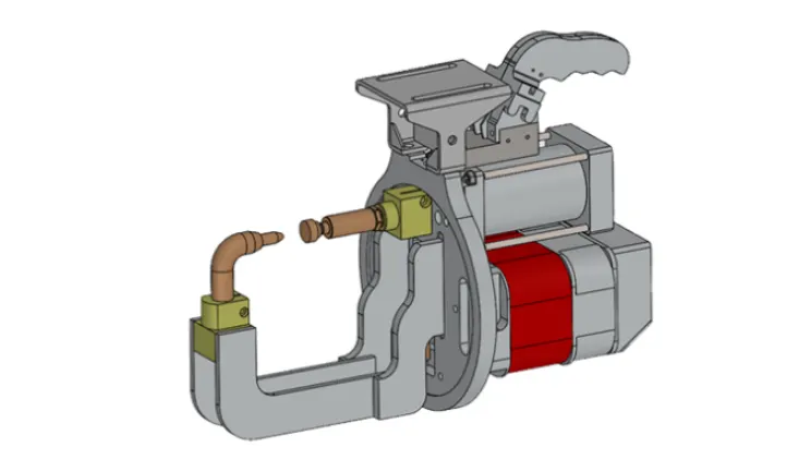
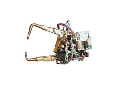
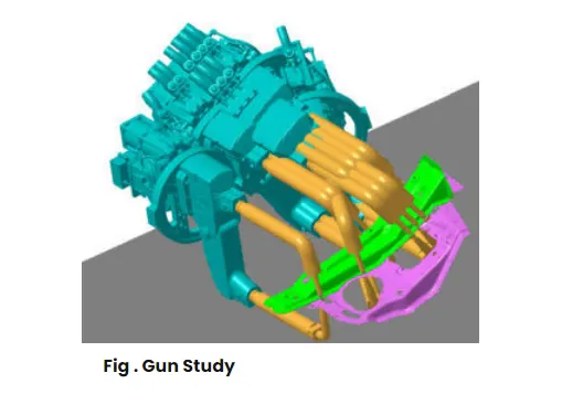
A5.Welding is a procedure that is commonly employed in the vehicle sector, and the requirements for the welding process are a continual development effort in any industry. Car Body-in-White (BIW) is a complicated/complex construction that is assembled through welding. The first step before beginning the design of a welding fixture is to determine the placement of the spot welds. The location and orientation of the fixture's other important units, such as clamps and locators, are determined by the weld spot distribution. The graphic above depicts the weld gun used for spot welding, as well as the weld matrix and weld position where the welding will take place.
There will be two kinds of weld spots: geo weld points and respot weld points. The geo weld spots are welded in the first stretch, and the respot welded points are welded in the second stretch. Gun study entails studying the weld gun, which is a portable equipment for semiautomatic welding of parts/components that will be utilized for the operation depending on the size of the part, thickness of the part, and so on. If the weld gun falls to the fixture unit then redesigning of that unit or the repositioning of that unit is done and again confirms whether the gun is falling or not. Fixtures are redesigned if the gun falls to the fixture unit, the weld spot positions remains same.
Q6. What are the points need to consider during the gun study?
A6.Weld gun study is very time consuming process and presented below:
The points to be considered during the gun study are ;
The total time required to complete all of the weld spots is determined by the number of weld spots on the panel and the time required to spot each weld. The weld spot's axis along the welding direction must be normal to the weld surface. If we have one or more device models and want to programme them, we can mimic the behaviour of each model in the work cell over time. Sequences are used to code instructions for each device.
The motion, manipulation, and operation of the devices are defined by the sequence. Cycle time for each device associated with sequences can be calculated based on the distance of each tag point from the home location, motion type, speed, and acceleration. The robot cycle time is properly computed in this manner. After all of the devices have been sequenced, a simulation is conducted with " collision check " enabled to ensure that the welding procedure is collision free.
Q7. What is pneumatic routing?
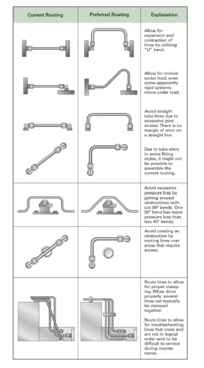
A7.Pneumatic systems should be leak-free and efficient. Sometimes they aren't because of incorrect tube line routing caused by either a lack of understanding or cutting cuts on planning time, or both. Planning tube line routing takes time, but it can pay off handsomely, especially in complicated systems. Routing should be developed as the next step in system design after sizing the tube line and selecting the necessary fittings.
Routing should be designed with clamping in mind. Appropriate design logically leads to proper clamming. Several lines can frequently be clamped together. Consider troubleshooting and maintenance: focus on logical design and avoid crossed lines. Design the tube line routing to minimize the possibility of users standing or climbing on plumbing.
Q8. What is the solenoid valve?
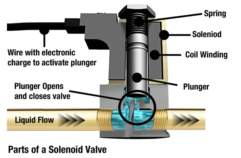
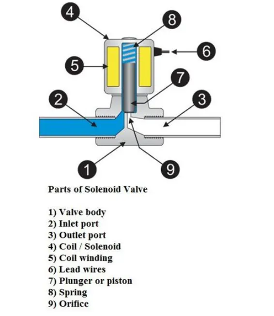
A8.A solenoid valve allows or prevents flow through a valve by opening or closing an aperture in the valve body. A plunger opens or closes the aperture by raising or lowering it within a sleeve tube when the coil is activated. As seen in the diagram below, solenoid valves are made comprised of a coil, plunger, and sleeve assembly. A solenoid valve is an electromechanical valve. Solenoid valves differ in the features of the electric current they use, the strength or magnetic field they generate, the mechanism they use to regulate the fluid, and the type and attributes of the fluid they control. Mechanisms include linear action, plunger-type actuators, pivoted-armature actuators, and rocker actuators.
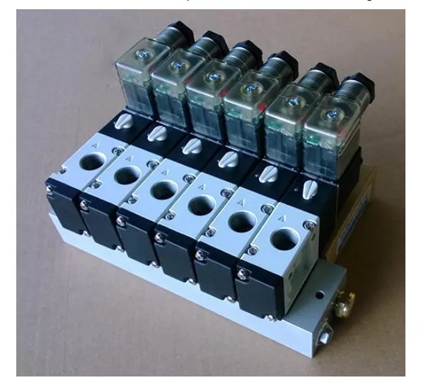
On a manifold, multiple solenoid valves can be grouped together. Solenoid valves are the most commonly used control elements in fluidics; their functions include shutting off, releasing, dosing, distributing, and mixing fluids. Solenoids provide fast and safe switching, high reliability, long service life, medium compatibility of the materials used, minimal control power, and a compact design.
Q9. What is the valve bank?
A9.A solenoid valve bank is a grouping of solenoid valves. A shared inlet port, a single servo line to each pneumatic valve, and separate vent channels for each solenoid will make up the valve bank. A valve bank is a group of individual valves that operate distinct consumers. Many valve sections make up the BA directional valve bank. These components can be used to make compact control blocks. By selectively energising the matching solenoid, the valve is triggered, allowing servo air to enter the valve's servo port. The solenoid is de-energized by venting the valve's servo port to ambient to return the valve to its fail-safe state. The design architecture makes it easy to choose between two and six solenoid valves.
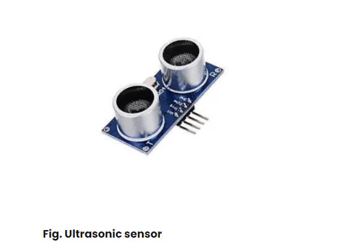
Q10.What is sensor & brief about its application in automobile?
Q11.What are the types of the sensor?
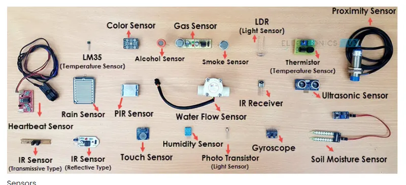
A11.The following is a list of different types of sensors that are commonly used in various applications:
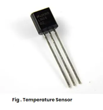
Temperature sensor
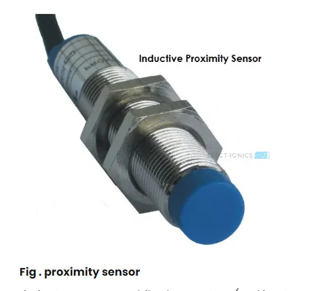
Proximity sensor
Accelerometer
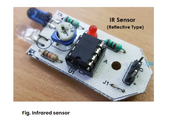
IR sensor (Infrared sensor)
Pressure sensor
Light sensor
Colour sensor
Humidity sensor
Tilt sensor Flow and level sensor
Q12.What are the fundamental points that need to be consider while designing or selection of sensors?
A12.The following are the most important factors to consider while building a sensor: