Week 8:- 3D Finishing - Challenges 1

REPORT
Assignment-11
By Ravi Ahuja
Q1.
3D finish process is the process where design is being comletely finish and to be ready for final simulation and 2d detailing.
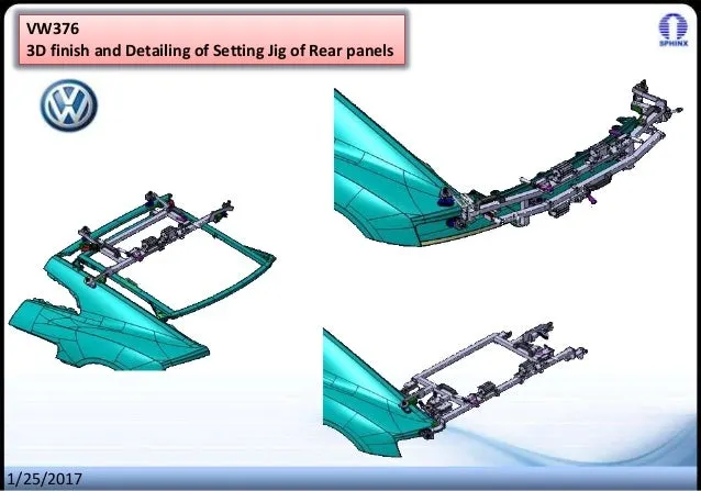
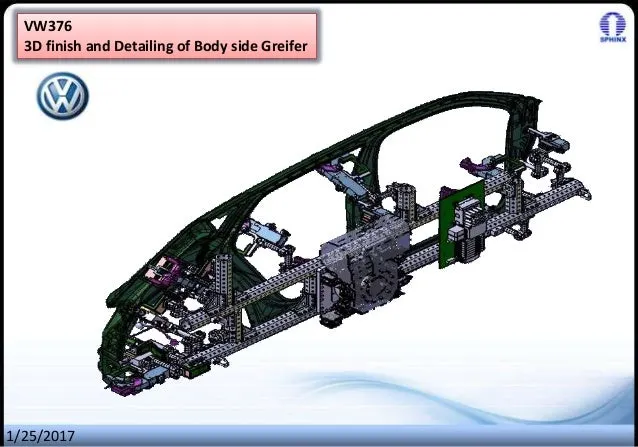
While finishing the design the noinality of holes is checked which ensures the easy assembly of al units.
The hole cinnectivity and holes sizes are cheked which ensures the easy assembly of parts.
The gaps between the different units are checked to ensure the proper individual working of different units.
Fasteners are implemented as per the hole size and the standard color codes as per the customer requirement are applied to differentiate the type of hole wheather its a simple hole, threaded hole or counterbore hole.
Renaming of the assembly and the part is done to give every part a different identity so everyone can identify in which assembly this part is going to be fit.
After doing all these things the model is set for simulation and 2D detailing.
Q2.
Following points are taken into consideration while finishing the design.
- Hole concentricity and hole sizes: All parts hole concentricity should be checked for east assemblywhile finishing the parts.
- Matching area: The machinig area is every part should be defined and the machning area should be highlighted by using standard color mode.
- Nominality: All units dimnesions should be maintained nominal to facilitate easy assembly of the unit.
- Holes coloring standard: Color code standard as per the customer requirement should be applied in the 3D finishing.
-Pneumatic layouting: Pneumatic layouting is collection of different pneumatic pipe which works as a inlet to the pneumatic cylinder.
- Gaps checking: Proper gap should be maintained between units to mentioned between units to avoid the clash between the different units.
-Fasteners implementation: Fasteners should be implemented in all unit as per therequirement and load on the part.
-Aovoiding clash between different part: Prper gap should be maintained between parts to avoid the clash.
-Mylars splitting as per panel profile: Mylars splitting should be confirmed whle finishing the design.
Q3.
- A rough locator is a part designed to guide the operator, to locate the car panel on to the pins accordingly. A rough locator canbe of standard part or make part.
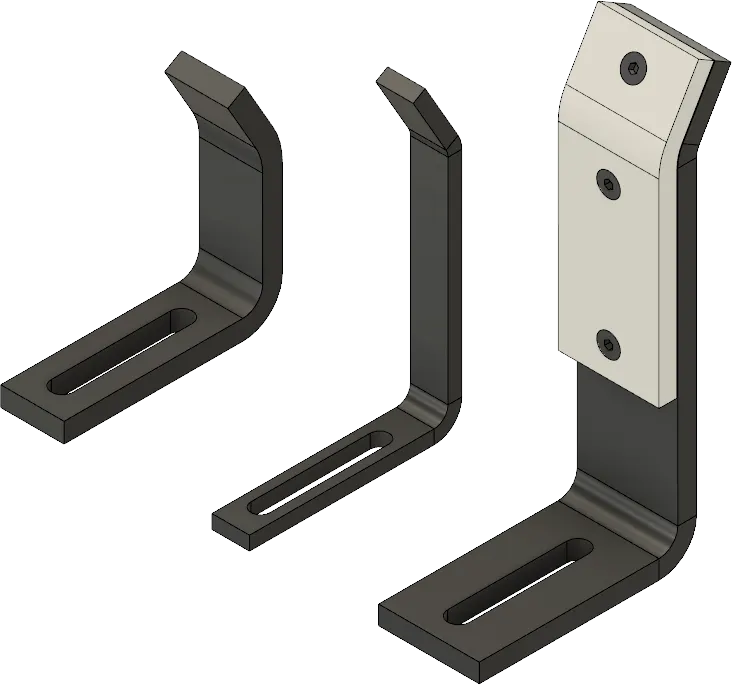
- Rough locators are used to help locate workpieces in the automtion processes. Locating refers to the desired location where you want the workpiece to be when it is getting worked on.
- The accuacy of the locating components directly affets the consistency and how the final product will come out. This is why these components are essentil to your setup.
- It can be called as fol proofing method also. Beacuse due to the rough locator the part can be located in incorrect location.
Q4.
Points needed to be considered while designing the rough locator.
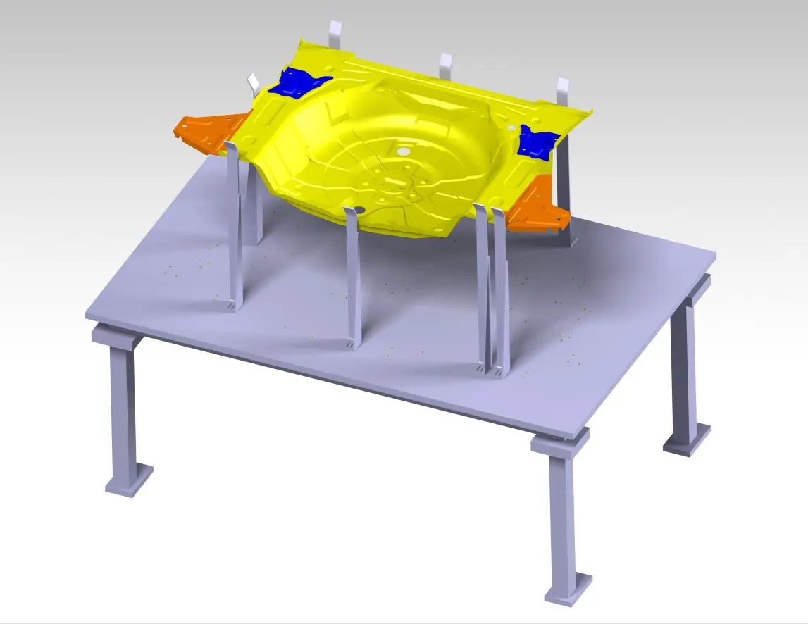
- Rough locator should be placed at the edges of the car panel, which it has to guide.
-rough locator has to be placed in the same angle of the car part edge with a minimum distance of 2-5mm from the edge of the car part.
-Rough locator should guide the panel in pin arresting direction.
Rough locator should start guiding the panel before 10 to 15mm to start of the pin arrangement.
Rough locator should be designed with entry angle for the car panel. Generally it ranges between 30-45 degree.
-Rough locator should be designed with 2 slots to mount the easy adjustments.
-Slots should be in the direction of car part guiding.
Q5.
-Welding is predominantly used in automobile industries and requirements for fixtures that ease the welding process is a development task in any industry.
-Car BODY-in-white is a complicated steel structure including 300-500 sheets with complexx shape and are assembled by means of welding in a high rhythm through 55-75 robotic work stations.
-The formost step taken before starting the design of welding fixtures is to arrive at the spot weld locations. The location and orientation of other critical units of the fixture including clamps, locators etc. are decided based on the weld spot distribution.
It includes the study of weld matrix and the weld point positions. There are two types in weld point one is geo weld points which ensures the geometry of the assembly and second is the re spot weld points which adds strength to the already welded parts.
It includes the study of the weld gun which is going to be used for the operation depending on the size of the part.
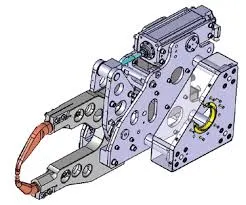
-In weld gun study the gun is going to be used while spot welding is checked over the panel by using the 3D software.
-The fixture is designed for the car panel to hold it on the position, the weld gunposition is checked over the predefined spot weld points.
-The weld gun fall to the fixture unit the redesigning of that unit or the repositioning is done agai confirmed whether the gun is falling or not.
-Fitures are redesigned if the gun falls on the fixture unit, the weld spot position remains same.
-The weld spots are dscribe on the prescribed loactions. The axis of weld spot welding direction must be normal to theweld surface.
Q6.
-Weld gun study is very time consuming process, the entire welding cycle time study depends on the no. of spots and weld gun study.
- The axis of weld spot along welding direction must be normal to the weld surface.
-The no. of weld spots for the panel The time required to spot each weld and the total time required to complete all the weld spots.
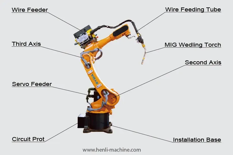
-If we have one more device models and we want to program; the each model in the work cell can be simulated over time. Instructions for each device are coded y giving sequences.
- After sequencing allt he devices a simulations is runwith collision check ON and made sure that welding operation is collision free.
Q7.
Pneumatic tubes (or capsule pipelines, also known as pneumatic tube transport or PTT) are systems that propel cylindrical containers through networks of tubes by compressed or by partial vaccum. They are used for transporting solid objects, as opposed to conventional pipelines, which transport fluids. Pneumatic tube networks gained acceptance in the late 19th and early 20th centuries for offices that needed to transport small, urgent packages (such as mail, paperwork, or money) over relatively short distances (within a building or, at most, within a city). Some installations grew to significant complexity, but were mostly superseded. In some settings, such as hospitals, they remain widespread and have been further extended and developed in the 21st century.
A small number of pneumatic transportation systems were also built for larger cargo, to compete with more standard train and subway systems. However, these never gained popularity.
Q8.
Solenoid valve- A solenoid valve is an electrically controlled valve. The valve features a solenoid, which is an electric coil with a movable ferromagnetic core (plunger) in its center. In the rest position, the plunger closes off a small orifice. An electric current through the coil creates a magnetic field.
- Only used for clean liquids and gases.
- Indirect operated valves require a pressure differential to function.
- Are used to close, open, dose, distribute, or mix the media with 2 or more inlets/outlets.
- Fast acting.
- Options for manual overrides, ATEX, gas approval, media separation and more.
- Can get hot as it requires energy to switch and stay in that position (depending on type).
- Common in heating systems, compressed air, vacuum, irrigation, car washes, etc.
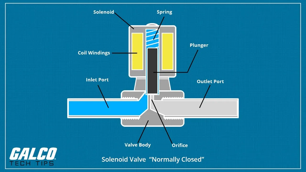
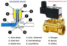
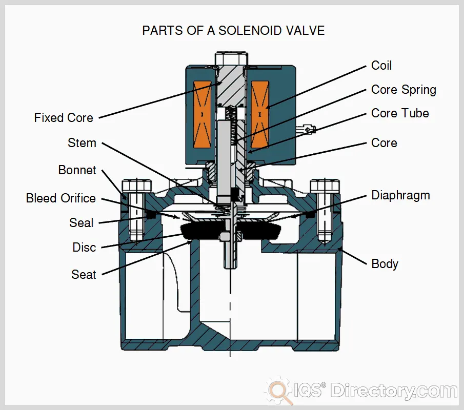
A solenoid valve, as mentioned earlier, can be separated into two major parts: the solenoid and the valve body. The solenoid is just one type in a variety of actuators such as manual, pneumatic, hydraulic and so forth. The solenoids have varying parts depending on the type of action required. The valve body components, on the other hand, are the same for every valve but with different designs and materials. Listed below are the general solenoid and valve body components.
-
Coil
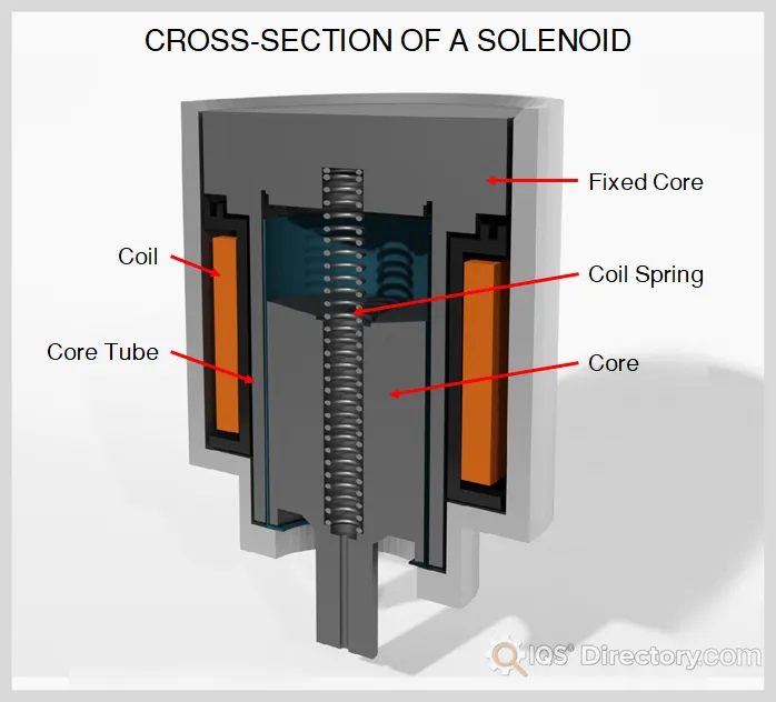
The coil is one of the main parts of the solenoid which consists of an insulated copper wire wound tightly around a core tube. As described earlier, a magnetic field is generated when current is applied.
-
Core
The core, also referred to as the armature or plunger, is the moving part of a solenoid. This is a soft magnetic metal; soft, meaning a ferromagnetic metal that can easily be magnetized and demagnetized at low magnetic fields. When the coil is energized generating a magnetic field, the core is attracted which opens or closes the valve.
-
Core Spring
The core spring returns the core to its original position when the magnetic field is removed. The core spring design and configuration in the solenoid assembly varies depending on the valve operation. In some designs, such as the latching type solenoid valves, it does not use springs to create a return action.
-
Core Tube
The core tube is where the coil is wound. This also acts as a soft magnetic core which improves the magnetic flux generated by the coil.
-
Fixed core
This is installed at the closed end of the core tube which also improves the magnetic flux. The material is also a soft magnetic metal.
-
Diaphragm
The diaphragm is a flexible material that isolates the solenoid assembly from the fluid. The diaphragm is designed to contain the pressure of the fluid.
-
Stem
The stem is part of the valve where the core or plunger is attached. As the core is attracted by the coil, the stem moves along with it actuating the valve.
-
Disc
The disc blocks the flow of fluid when the valve is closed. In some solenoid valve designs, diaphragms, bellows or pinch devices are used instead of a disc to block fluid flow. Depending on the application, the disc is usually made of corrosion and erosion resistant materials such as PTFE or stainless steel.
-
Seat
The seat is the orifice that presses against the disc when closing the valve. Like the disc, the seat may not be present depending on the valve design. The seat is also made of corrosion and erosion resistant material. Once the seat or disc is damaged, the valve will become passing and unable to stop flow.
-
Seal
The seal, like the diaphragm, isolates the solenoid assembly and the external environment from the fluid. Depending on the application and the process fluid, there is a variety of seal materials available such as PTFE, FKM, NBR and EPDM.
-
Bonnet
The valve bonnet seats at the top of the valve body. The core tube and stem extend through the bonnet and into the valve.
-
Body
The body is the main part of the valve which holds the diaphragm, disc, seat and the inlet and outlet ports.
-
Bleed Orifice
For indirect or semi-direct acting solenoid valves, a bleed orifice is installed on the diaphragm. Some valve designs use an equalizing hole. The bleed orifice enables the valve to use the line pressure to open or close the valve.
-
Pilot Channel
For indirect acting solenoid valves, a pilot channel is included into the valve body. This is where fluid flows from the top of the diaphragm and into the downstream side of the valve.
Q9.
A valve bank combines different valves for operating independent consumers. ... The intermediate plates type NZP make possible additional functions and contain, e.g., pressure-reducing valves, shock valves, load-holding valves etc. An intermediate plate can be inserted between the sub-plate and the valve.
Features and benets:
■ Sub-plates for exible combination of directional valve types with NG 6 (CETOP)
standard connection pattern
■ Valve bank can be ange mounted directly on the connection block of a compact
hydraulic power pack or connected as a separately arranged valve bank for pipe
connection
■ Pressure switches and/or any other monitoring elements can be connected directly
■ Additional elements, such as orices, throttles and check valves for connections P, R, A
and B can be integrated
■ Hydraulic accumulator can be mounted directly
Intended applications:
■ Clamping systems on machine tools and equipment
■ Process control on deforming machine tools
■ Brake and rotor adjustment modules on wind turbines