Week 8:- 3D Finishing - Challenges 1
1. 3D FINISH: A 3D finish is a process in which the final check of design feasibility is done just before simulation. In this process, a designer needs to make sure that all the units are placed properly using the 3-2-1 principle. They should be at a nominal distance from each other, and above the height of the fixture should be according to ergo-data. After validating all these points, the final simulation of the panel is done in which inspection for loading and unloading of the panel is done such that there is no class between the components while gun study. And then only the 2D detailing of the fixtures are done.
2. The points that need to be considered while doing 3D finish are as follows:
- All the holes should coincide and be concentric to each other with proper color coding for the holes i.e. "Blue" for Dovel pinholes, "Yellow" for Threaded holes, "Sea Blue" for non-threaded holes on the riser.
- Standard color for Machining parts should also be there i.e. "orange"
- All units should be at nominal dimensions to each other as well as to the edges of the base plate so that proper alignment of holes could be done.
- There should be no clash between components/units/weld gun study.
- Standard fasteners should be used.
- Pneumatic layout space should be available for pneumatic components routing.
- All sensors should be placed fully under the panel for accuracy.
3. Rough Locators are the part of the Base Unit that is used while manually loading the component. These are used when a component is loaded by a person rather than a robot to a fixture. It helps in guiding the panel for positioning and orientation using the Poka-Yoke principle.
4. The points that are needed to be considered while designing a rough locator are as follows:
- The height of the rough locators should not be more than that of ergo-data.
- The rough locators can be of rod-type or flat type depending on the usage
- For flat-type rough locators, the top face angle should be between 30 to 60 degrees.
- The top edge of the rough locator should be 10-15mm above the edge of the panel.
- A minimum gap of 2mm should be maintained between locators and panels.
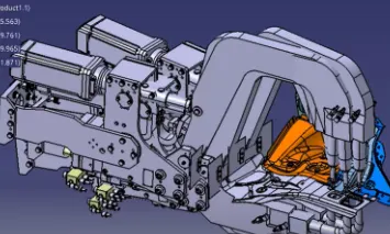
5. Gun study process is the process in which weld gun assembly is placed at the welded spots, which allows us to check the position of guns such that the robot could easily work on the panels without damaging any fixture component. Tolerance of +/- 5 degrees is given to weld guns for this study.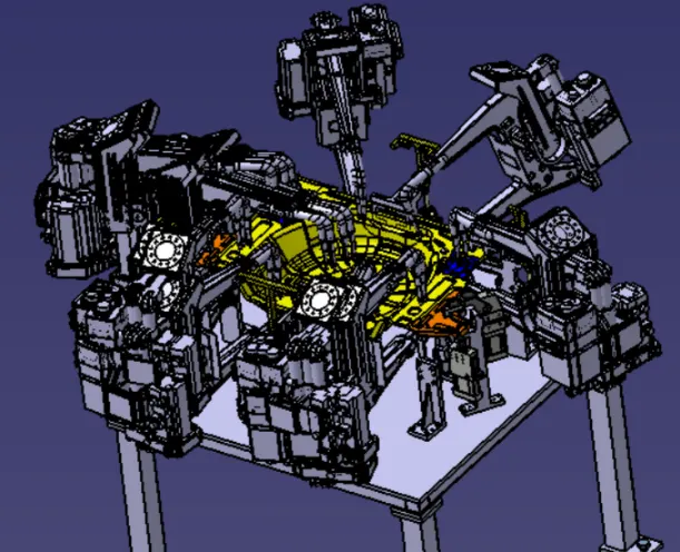
6. The points that need to be considered during gun study:
- Tolerance of +/- 5 degrees is given to weld guns
- Avoid clash between weld-gun components and fixture components.
- Data for weld spots should be given precisely such that it should have enough space tolerance to avoid clash with spot gun
7. A pneumatic routing is an open-loop duct which is a bought-out part through which the pneumatic cable a guarded to the solenoid valve in the valve box. It is used for low pressure to deliver less force compared to the hydraulic system. It is cheaper than a hydraulic system but the running cost for pneumatics is high.
Pneumatic routing is used to operate toggle clamps, pneumatic cylinders, pin cylinders, slides, etc. Cylinders are designed to operate at a maximum of 12-13 bar pressure, for this a pneumatic system that operates at 5-6 bar pressure is used.
Routing helps to keep pipes away from welding spatters to avoid wear and tear.
Common pneumatics are used of TUNKERS, CKD, FESTO
8. Solenoid Valve is used to actuate airflow in cylinders according to the sequence manually or through PLC. Each cylinder has its own Solenoid Valve which allows the air to flow through it and is sent to the valve box which has a common inlet and outlet for the system.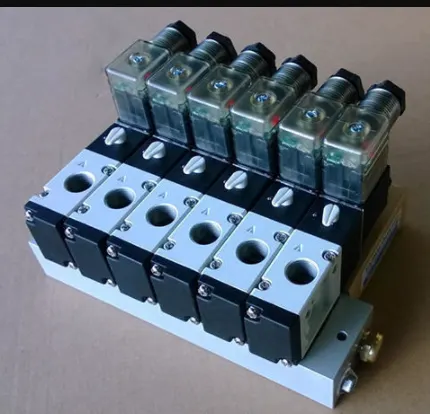
9. Valve Bank: It has "n" number of solenoid valves which has a common inlet and outlet for airflow.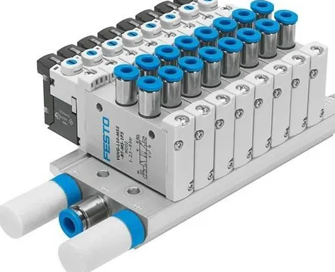
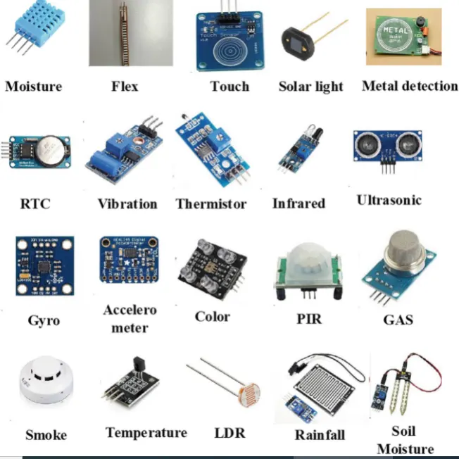
10. A Sensor is a device that is used to sense the objects around us i.e. to see them, to smell the odor, to taste the eatables, etc. In general, a sensor is a device that detects, measures, and converts a physical quantity into a signal that can be read by an observer with help of an instrument.
There are various applications of sensors in automation:
- Temperature sensors: A device that is used to collect the information concern to temperature from a resource and changes it to the form that is readable in another device by the user.
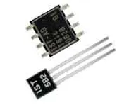
- Pressure sensors: A device that apprehends pressure and changes it into an electrical signal where quantity depends upon the pressure applied.
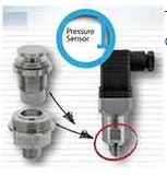
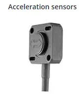
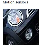
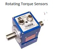
- MEMS sensors: MEMS stands for Micro-Electro-Mechanical Systems. These sensors convert the mechanical signals into an electrical signal. eg: Acceleration sensor, Motion sensor, Torque sensors, etc.
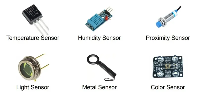
11. Types of Sensors:
- Temperature sensor
- Proximity sensor
- IR-Infrared Sensor
- Ultrasonic sensor
- Pressure sensor
- MEMS sensor
- Light sensor
- Colour Sensor
- Position sensor
- Half effect or Magnetic sensor
- Flow and Level Sensor
12. Fundamentals need to consider while designing or selecting of a sensor:
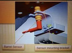
- Every single loose panel which is being welded in a tool should be sensed.
- Each panel should be sensed by 1 or 2 sensors depending on the size of a panel.
- If two sensors are used then sensors should be placed diagonally opposite to each other in that panel.
- Every sensor should be mounted in a 3-way adjustable direction.
- A sensor should be placed fully under the panel, but even a single edge of the sensor should be open to the user.