Week 8:- 3D Finishing Challenge 2
DESIGN OF FIXTURES FOR CAR PANEL
1) INTRODUCTION
The fixture is a device used for holding and positioning of panel, locating and setting of the tool but no guidance will be given to the tool. The fixtures are the units that are used to constrain the car panel in the manufacturing process. The fixture design consists the data of the car panel, location of the fixture, robot arm data, weld spot and spot gun data. There are different types of fixtures that are used in the industries for constraining the car panel. The 12 DOF are acting on the panel when it is in space. There are 6 translation and 6 rotation in X, Y and Z coordinates. In order to restrict the motion of the panel, all the 12 DOF needs to be arrested.
The different types of fixture units that are utilized to stop the motion of the panel in all the DOF are:
- a) Fixed pin unit
- b) Retractable pin unit
- c) Clamp unit
- d) Swivel unit
- e) Base unit
- f) Rough Locators
The principle that is used for constraining all the DOF are 3-2-1 principle. This is used for locating cartesian coordinate system of components. The 3,2,1 are the number of pins provided in three mutually perpendicular planes for arresting required number of degrees of freedom of the panel.
3 pins – 5 DOF – (4 Rotation + 1 Translation)
2 pins – 3 DOF – (2 Rotation + 1 Translation)
1 pin – 1 DOF – (1 Translation)
2) OBJECTIVE
The objective of the project is to design the fixture that restricts the motion of the panel in all the DOF. Designing the fixed pin unit, retractable unit, clamp unit, swivel unit and base unit in the CATIA V5 following all the design considerations.
3) DESIGN METHODOLOGY
The fixture units for the given car panel are modelled in the CATIA V5. The feature tree is named as “P01_Z01_ST010_00_00” in which
P01 – Project 1
Z01 – Zone 1
S010 – Station 10
00 – Unit number
00 – Part number
For every unit the unit number and part number changes but the project, zone and station remain same.
1) FIXED PIN UNIT
Fixed pin unit is a unit designed to locate the car panel using pins.
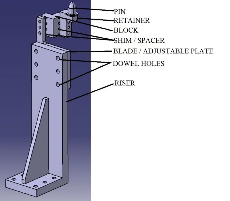
The parts of fixed pin are:
- Pin
- Pin retainer
- Shim / spacer
- Block
- Blade or Adapter plate
- Riser.
- The unit is titled with the “P001_Z01_ST010_06_00”. All the parts in the feature tree of the CATIA must follow the same process for easy identification of parts in the assembly.
- The centre of the hole is taken and the pin outline is modelled as per the standards.
Note: If there are any standards parts, it is advisable to use the standards parts as many as possible.
- The blocks are modelled in such a manner that the pin can be adjusted in longitudinal and translational direction.
- A 5 mm space is provided between the block and retainers as the shims or spacer blocks are present.
- The dowel holes are present in all the parts of the pin units which are to be assembled with tolerance should be designed with 2 dowels and at least of 1 to 6 threated / free hole (depends on size). And to be fine machined for the mounting surface with 3 to 5 mm step machining.
- The blade is a plate which connects the riser to the block, usually the blades are standard parts if needed can be designed.
- The riser is a part on which all the parts of a unit are mounted, and is mounted on the base plate of a tool. In general, the riser can either be make part or a standard part.
2) RETRACTABLE UNIT
Retractable pin unit is a unit designed to locate the car panel using pins. It is mostly used where the removal of the panel is complicated.
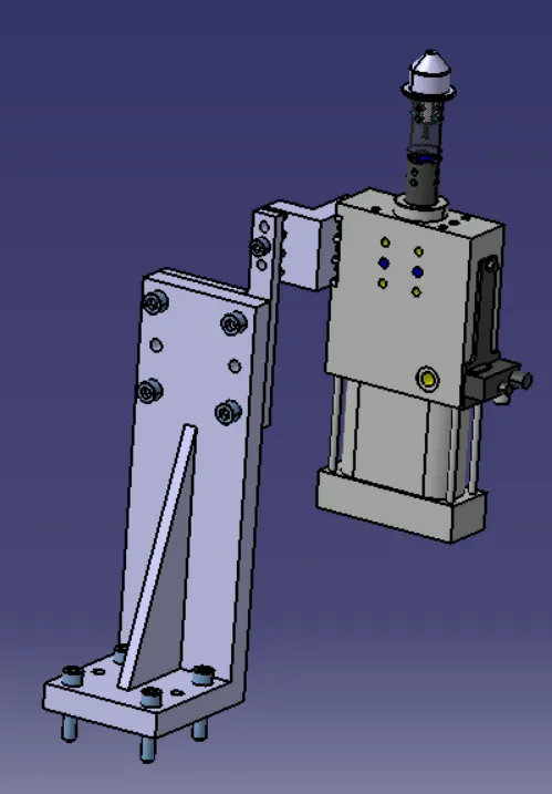
The parts of retractable pin are:
- Pin
- pneumatic cylinder
- Shim / spacer
- Block
- Riser.
- The units are titled with the “P001_Z01_ST010_07_00”, “P001_Z01_ST010_10_00”, “P001_Z01_ST010_11_00”. All the parts in the feature tree of the CATIA must follow the same process for easy identification of parts in the assembly.
- The centre of the hole is taken and the pin outline is modelled as per the standards.
Note: If there are any standards parts, it is advisable to use the standards parts as many as possible.
- The blocks are modelled in such a manner that the pin can be adjusted in longitudinal and translational direction.
- A 5 mm space is provided between the block and retainers as the shims or spacer blocks are present.
- The dowel holes are present in all the parts of the pin units which are to be assembled with tolerance should be designed with 2 dowels and at least of 1 to 6 threated / free hole (depends on size). And to be fine machined for the mounting surface with 3 to 5 mm step machining.
- The riser is a part on which all the parts of a unit are mounted, and is mounted on the base plate of a tool. In general, the riser can either be make part or a standard part.
3) CLAMP UNIT
A Clamp unit is a unit designed to clamp/hold the car panel with NC blocks/ Mylars/ Rest by using a pneumatic clamp cylinder.
The parts of clamp unit are:
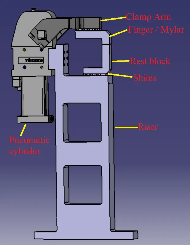
- Rest block /Mylar
- L - block
- Shim / spacer
- Blade or Adapter plate
- Riser.
- Clamp Arm
- Pneumatic cylinder
- The units are titled with the “P001_Z01_ST010_08_00”, “P001_Z01_ST010_09_00”. All the parts in the feature tree of the CATIA must follow the same process for easy identification of parts in the assembly.
- The standard pneumatic cylinders are copies and pasted into the project folder. These files are downloaded from Tunkers website.
- The L- blocks / Mylars / Rest blocks are modelled in such a manner that there won’t be any movement of car panel in the transverse direction. The clamp unit restricts the transverse direction translation and rotation.
- Clamp arm is a bought-out part, to which all the movable parts are fixed. In general, a clamp arm is a part of clamp cylinder. Clamp arms are different for different bore of cylinders. Clamp arms are available in different hole patch. Clamp arm are available as: Middle arm – A10, Right arm – A11, Left arm – A12.
- A 5 mm space is provided between the clamp arm and mylars as the shims or spacer blocks are present.
- The dowel holes are present in all the parts of the pin units which are to be assembled with tolerance should be designed with 2 dowels and at least of 1 to 6 threated / free hole(depends on size). And to be fine machined for the mounting surface with 3 to 5 mm step machining.
- Clamp cylinder is a pneumatic device works with pressurised air. The clamp cylinder is used to open and close the parts fixed to the clamp arm fixed to the clamp body. Clamp cylinders are in general 40,50,63 and 80 bore capacity. Opens up to 135° for horizontal clamp mounting. Opens up to 105° for vertical clamp mounting.
- The riser is a part on which all the parts of a unit are mounted, and is mounted on the base plate of a tool. In general, the riser can either be make part or a standard part.
4) SWIVEL UNIT
A Swivel Clamp unit is a unit designed to clamp/hold the car panel with NC blocks/ Mylars/ Rest by using a swivel cylinder.
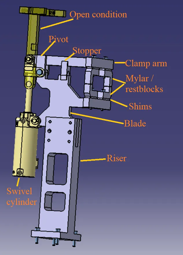
The parts of clamp unit are:
- Rest block /Mylar
- L - block
- Shim / spacer
- Blade or Adapter plate
- Riser.
- Clamp Arm
- Swivel cylinder
- The project is titled with the “P001_Z01_ST010_01_00”, “P001_Z01_ST010_02_00” “P001_Z01_ST010_03_00”. All the parts in the feature tree of the CATIA must follow the same process for easy identification of parts in the assembly.
- The swivel cylinder (CKG-1B-63-100Y) is imported as the name suggest the stroke of the cylinder in y-direction is 100 mm, bore of the cylinder is 63 mm.
- The L- blocks / Mylars / Rest blocks are modelled in such a manner that there won’t be any movement of car panel in the transverse direction. The clamp unit restricts the transverse direction translation and rotation.
- Clamp arm is consisting of pivots connected to blade and swivel cylinder. The open condition of clamp arm must be below the stroke length of the cylinder and exactly in the line to the swivel cylinder in vertical direction.
- A 5 mm space is provided between the clamp arm and mylars as the shims or spacer blocks are present.
- The dowel holes are present in all the parts of the pin units which are to be assembled with tolerance should be designed with 2 dowels and at least of 1 to 6 threated / free hole(depends on size). And to be fine machined for the mounting surface with 3 to 5 mm step machining.
- Blade are modelled in the way that; it gives support to the bottom rest blocks and also connects the cylinder. Stopper is present in the blade which helps to stop the clamp arm at a certain distance in the closed condition.
- The riser is a part on which all the parts of a unit are mounted, and is mounted on the base plate of a tool. In general, the riser can either be make part or a standard part.
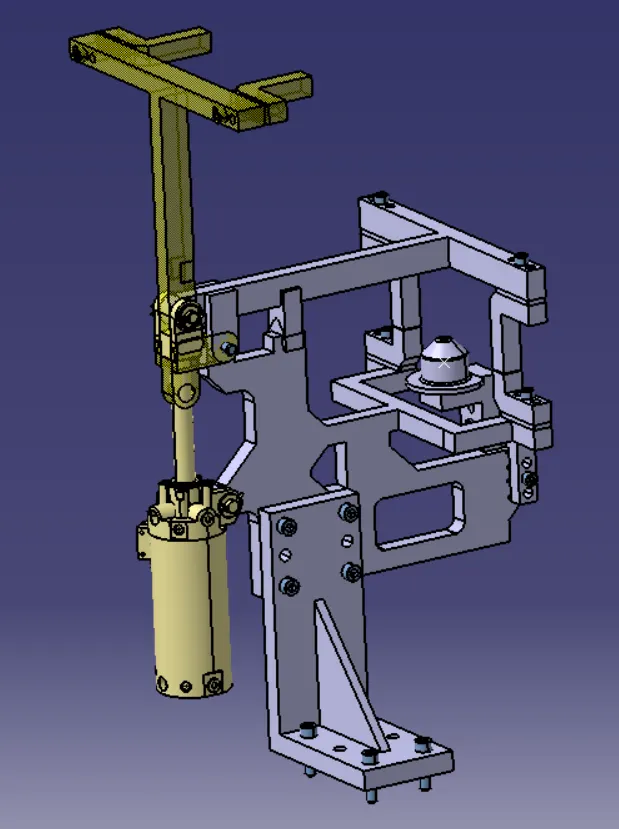
5) PIN-SWIVEL CLAMP UNIT
6) BASE UNIT
A Base unit is a unit designed to mount all the other units(Clamp, pin, rest units) of the tool, also other parts necessary for a tool like pneumatic valve box, trunking cable path will be mounted on to the base unit.
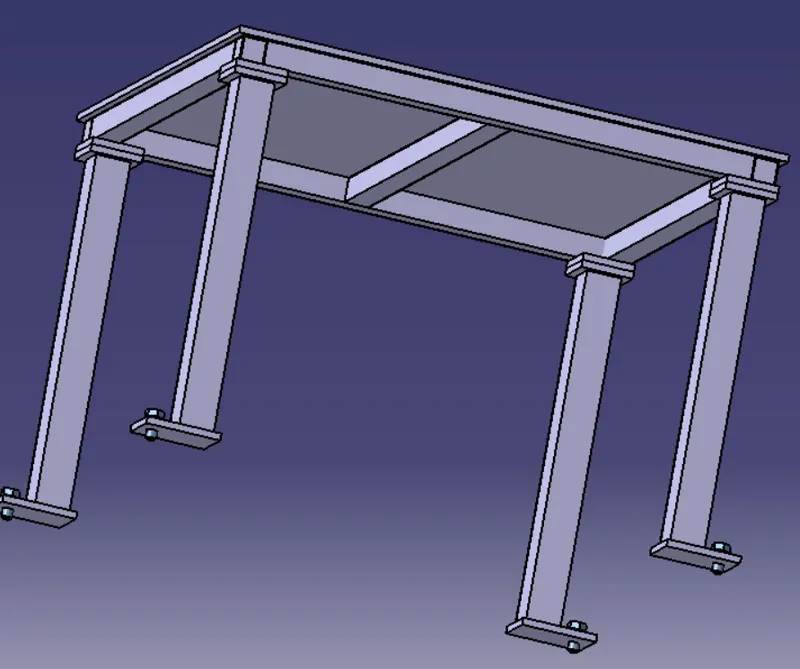
1) A Base unit should cover all the units with its outer periphery including openings.
2) A base plate is preferred to be designed with respect to BCS coordinates.
3) A base plate should be drilled with datum holes/measuring holes in line with a pitch of 1000 mm in general.
4) Number of datum holes is dependent on the size of the base plate.
5) Datum holes must be drilled in nominal values of coordinates and in terms of 50 and 100.
6) Datum holes should be drilled with diameter 100 mm away from other units.
7) Datum holes should be covered with cover plate.
8) There must a minimum space for the trunking channels.
9) The weld gun position and the weldment have to be checked. A minimum of 5 mm gap must be present between the gun and the units.
6) ROUGH LOCATORS
- i) Rough locators are basically used where manual loading of panels are to be implemented on the fixture.
- ii) These are used to guide the panels in correct position and orientation.
iii) These also help for proper poka-yoke, which means to avoid errors.
- iv) Materials used for rough locators are mild steel or similar metal.
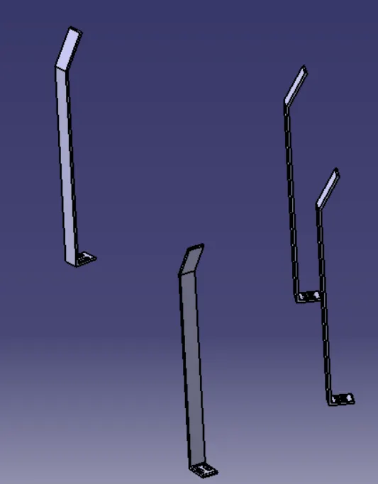
Points to be considered while designing rough locators:
- a) Height of rough locators should not be more than the permissible ergo height of the fixture.
- b) The entry point/ top point of the rough locators must be 10 mm to 15 mm above the panel surface.
- c) Rough locators should have adjustment in the direction of guiding plane.
- d) 2 mm gap to be maintained b/w rough locators and panel at the time of design and we can provide adjustment of 5-10 mm in the positive or negative direction of guide plane.
- e) Rough locators can be rod type or flat type, depending upon the standards and other conditions.
6) 3D-FINISH
3D finish is the process where design is completely finished and to be ready for final simulation and 2D detailing.
Points to consider:
- a) Hole concentricity and sizes has to be check for the rest blocks, mylars, blades and riser. All the holes must be concentric.
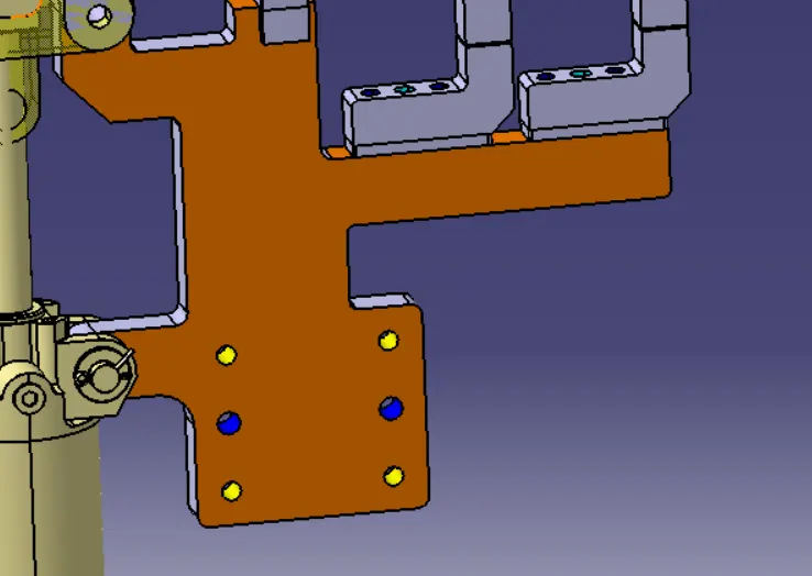
- b) If any surface of a part comes in contact with the other surface of the part, the surface has to be machined. To indicate the machined surface light brown color is indicated in the design.
- c) All the units must be in nominally designed. The pin is anyhow fixed so the pin is considered as the reference point and all the unit surfaces must be in nominal with the pin unit.
- d) Pneumatic cylinder pipes, wires from different unit has to be done in pneumatic lay-outing.
- e) There should be adequate gaps between the units and the weld gun.
- f) All the hardwares required for the units has to be checked. It helps in documenting the project.
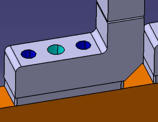
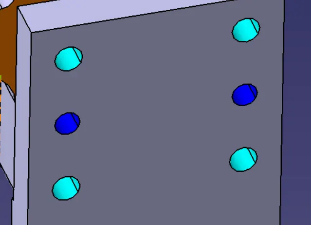
- g) Holes must be colored as per the requirements. The dowel holes must be sky blue color, open holes must be dark blue color and threaded holes must be yellow color.
- g) The parts and assemblies must be properly named as per the company standards.
4) RESULTS AND DISCUSSIONS
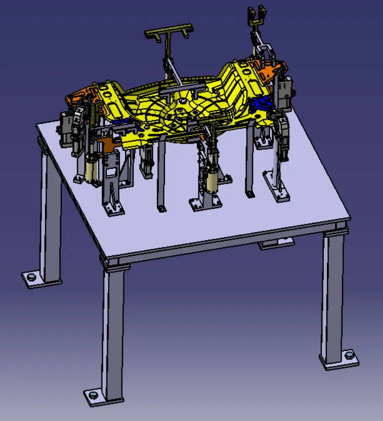
1.The units are designed well in according with 3-2-1 principle. The positioning and locating the panel is studied.
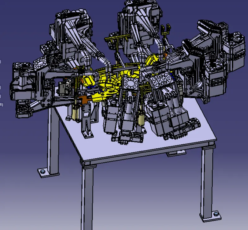
- The weld gun is placed at the locations of the weldments. The weld gun position is not collapsing with any of the unit. The weld gun cloud is also shown in the design.
- The rough locators are designed and placed where it is required.
- 3D finish of the fixtures are completed.
5) CONCLUSION
The fixture is designed for the car panel with all the design considerations. The positioning and locating the car panel is done.