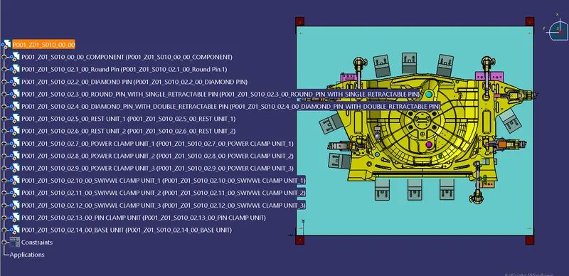
Week 8:- 3D Finishing Challenge 2
AIM:
- Perform 3D finish for all units of Assembly design.
- Create Rough locators for Assembly.
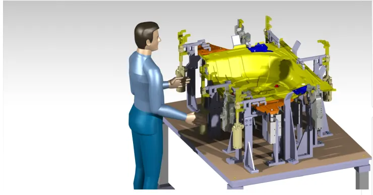
3D FINISH: The 3D finish is the process where the design is completely finished & to be ready for final simulation & 2D detailing.
- In 3D finishing we perform and ensure the following points:
i. Hole concentricity & hole sizes- All parts Hole concentricity is checked & confirmed while finishing the parts.
ii. Machining Area- The machining area in every part is defined & the machining area is highlighted by using orange color.
iii. Nominality- All unit dimensions are maintained nominal to facilitate easy assembly of the unit.
iv. Holes coloring standard- Color Code standard used in the 3D finishing
- Cyan - Simple Hole
- Yellow - Threaded Hole
- Orange - Machined area
- Blue - Dowel pin Hole
v. Fasteners implementation- Fasteners are implemented in all units as per the requirement & load on the part.
vi. Avoiding clash between different parts- Proper gap is maintained between parts to avoid the clash.
vii. Mylar splitting as per panel profile- Mylar splitting is confirmed while finishing the design.
viii. Proper renaming of parts/assemblies as per standard-proper renaming of parts & assemblies are done while finishing the design hence we can identify each & every part easily with a unique identification.
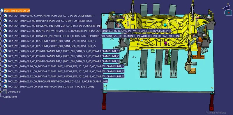
1 Renaming and Structuring of the design tree:
- Renaming the design tree is done. and structuring the design tree in a way that is simple to identify the units. some units use multiple times those are easy to identify by their name.
2 Base Unit:
- Renaming of parts and structuring design tree
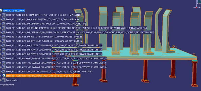
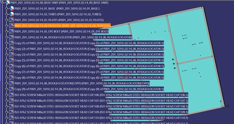
- Threaded hole and dowel holes making nominal and color-coding are done so easy to distinguish holes.
- Threaded hole (Yellow), clearance hole (Sky blue), Dowel Hole(Blue), Machining surface(orange).
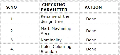
| S.NO | CHECKING PARAMETER | ACTION |
| 1. | Rename of the design tree | Done |
| 2. | Mark Machining Area | Done |
| 3. | Nominality | Done |
| 4. | Holes Colouring Standard | Done |
3 Retractable pin unit
- Holes are made to the nominal and Concentric to each other.
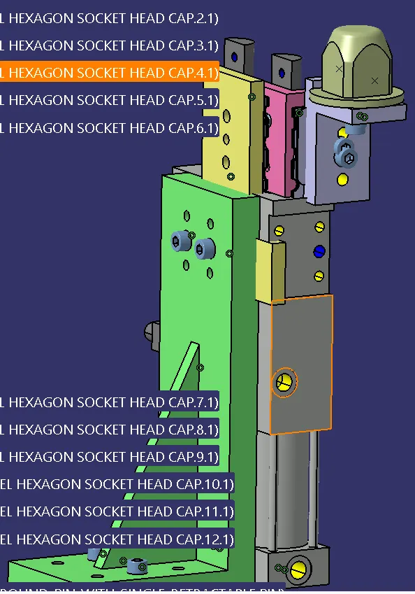
- The open position of the retractable pin is shown in yellow color
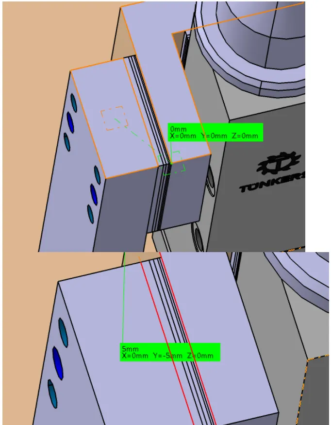
- The proper butting of the two parts is done
- color-coding is done as per the standards.
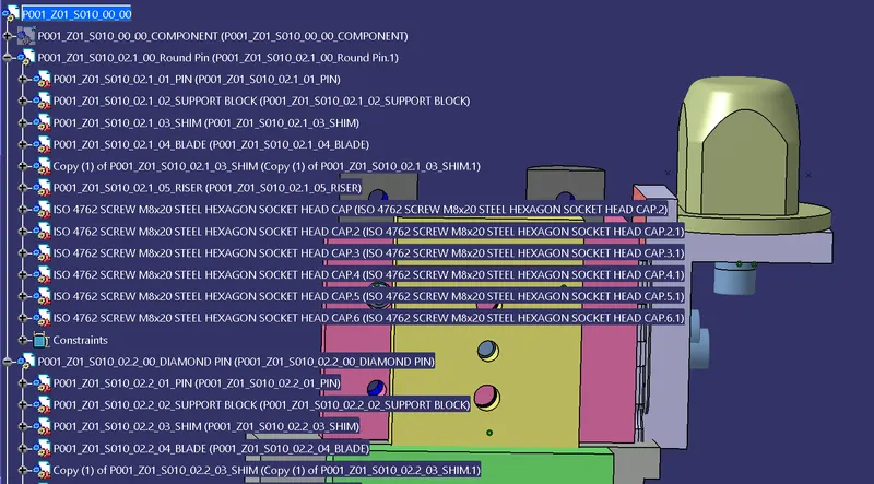
- structuring design tree renaming of parts is done.
- Below are some images after 3d finishing was done on the fixed pin unit.
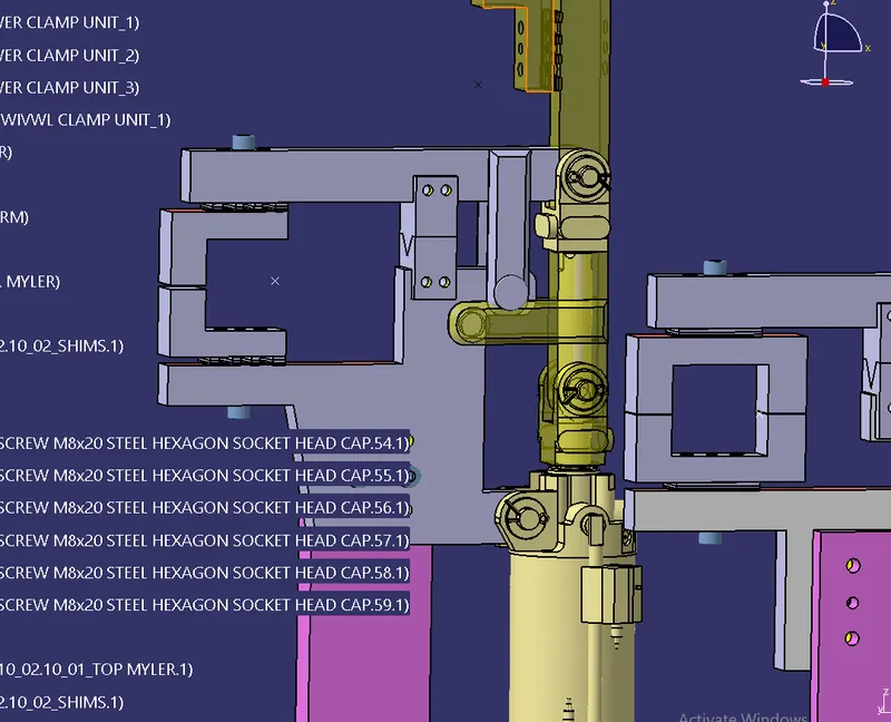
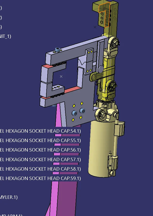
4 Swivel Clamp Unit
- Holes are made to the nominal and Concentric to each other.
- The proper butting of the two parts is done.
- Fasteners are implemented.
- Color coding is done as per the standards.
- Structuring design tree renaming of parts is done.
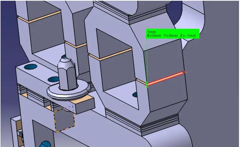
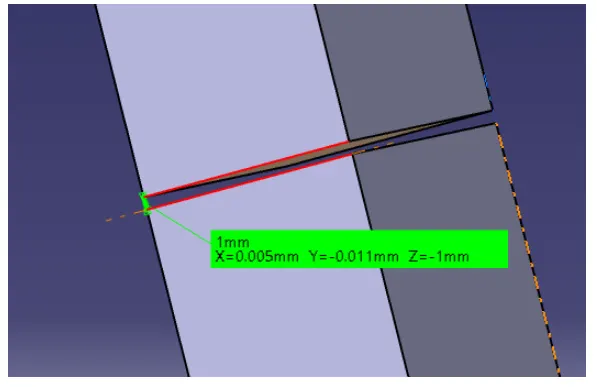
- Mylar splitting is done.
- The open position is shown in yellow color.
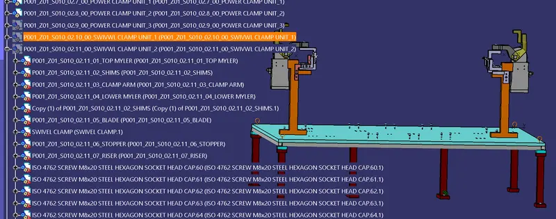
Below are some images after 3d finishing was done on the swivel Clamp unit.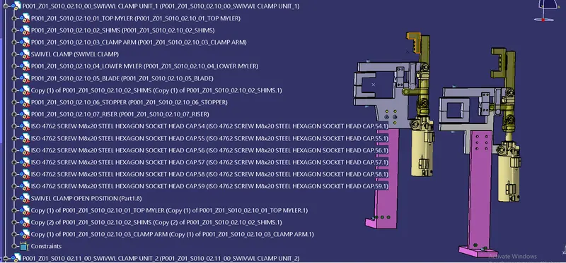
5. POWER CLAMP
- Holes are made to the nominal and Concentric to each other.
- The proper butting of the two parts is done.
- fasteners are implemented.
- color coding is done as per the standards.
- structuring design tree renaming of parts is done.
- mylar splitting is done.
- the open position is shown in yellow color.
- below are some images after 3d finishing was done on the Power clamp unit.
6 Rest Unit
- Holes are made to the nominal and Concentric to each other.
- The proper butting of the two parts is done.
- color coding is done as per the standards.
- structuring design tree renaming of parts is done.
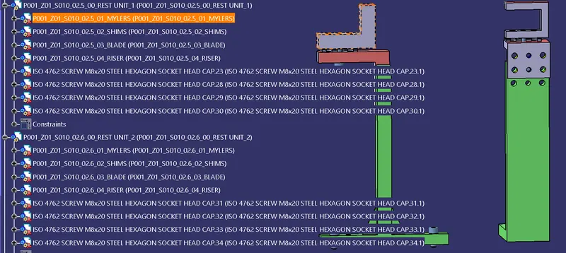
- mylar splitting is done.
- below are some images after 3d finishing was done on the Rest unit.
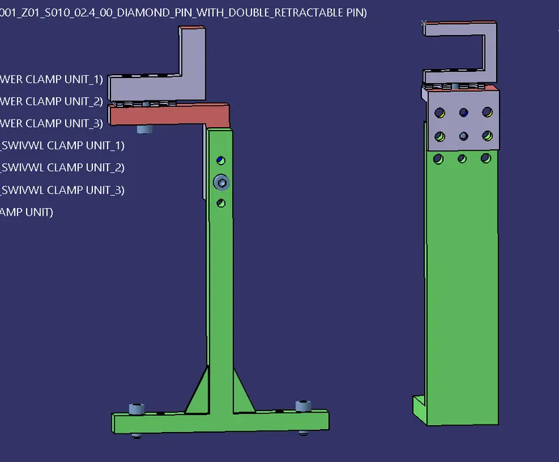
7 PIN CLAMP UNIT
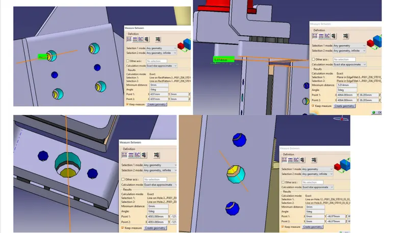
- Holes are made to the nominal and Concentric to each other.
- The proper butting of the two parts is done.
- color coding is done as per the standards.
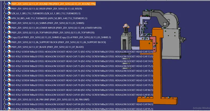
- structuring design tree renaming of parts is done.
- mylar splitting is done.
- below are some images after 3d finishing done on the Pin Clamp unit
8 Rough Locator
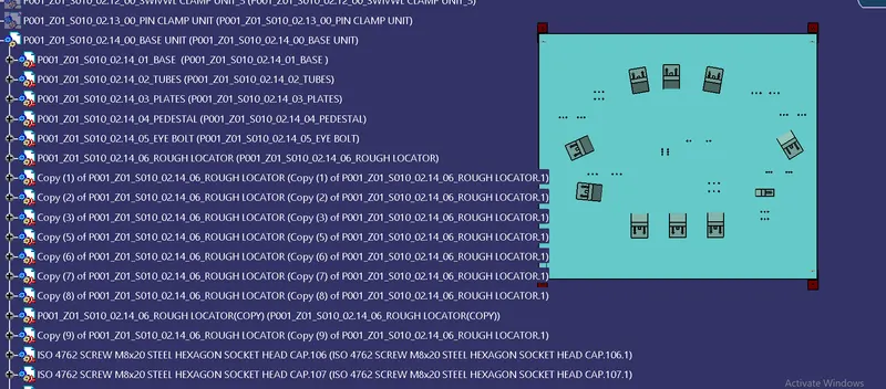
- Provide locator in 4 directions.
- Mention 0 mm gap between rough locator and panel.
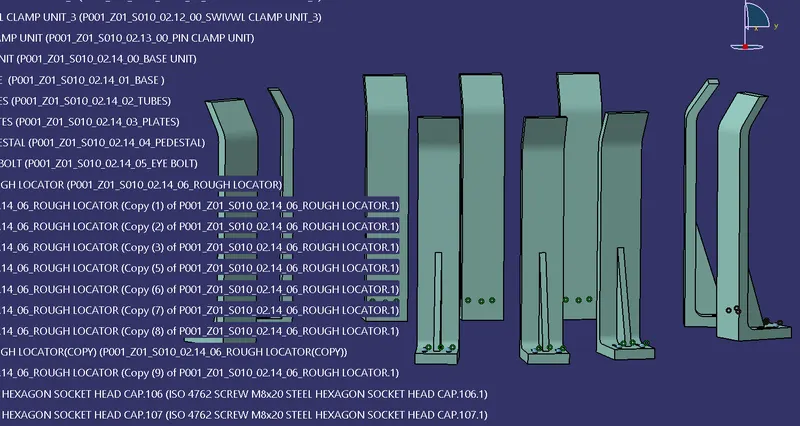
- here I use 10 rough locators as shown below.
FINAL OUTLOOK
.