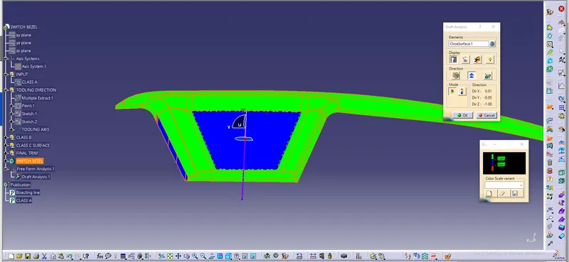
Week 8 - Challenge 3 - Switch Bezel Design
OBJECTIVE:
Create the Switch Bezel Plastic component through the given Class-A surface. To begin with, the tooling axis for the given Class-A Surface is created to meet the requirements of the draft angle and at the end perform the Draft analysis on the model.
The Thickness of the component is Considered as 3mm
INTRODUCTION:
Draft
• A draft angle is a slant that is applied to each side of most features of an injection molded part. In other words Draft is providing tapers on the product features such as walls ribs posts and bosses that he parallel to the direction of the release from the mold part ejection • The nominal draft is 3mm for plastic components and for automotive sheet metal components is 7mm
Tooling axis:
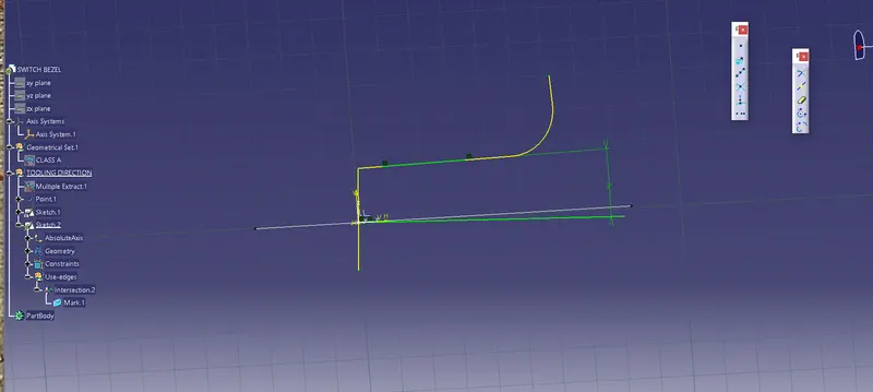
. It is defined as the direction in which the molds opens or core and cavity, with the help of tooling axis created along x and Y axes are used for creating the Main Tooling axis by using bisecting method
Creation of Dummy axis:
This is a normal line which we construct by analyzing the best possible direction(X/Y/Z axis) for the draft for the part, this axis is only for reference and is not used for Tooling Axis
Creation of Tooling Axis for Class A surface:
Taking the dummy axis as a reference, intersect the class A surface along the different axis (XY/YZ/ZX) Check for the possible places where the part might face difficulties while ejecting the component from the mold.
Lines are drawn at the places where the part boundary has difficulties
Later the Tooling axis in one direction (let's say X) is obtained by bisecting the lines drawn in the above process
DEVELOPMENT OF CLASS B SURFACE:
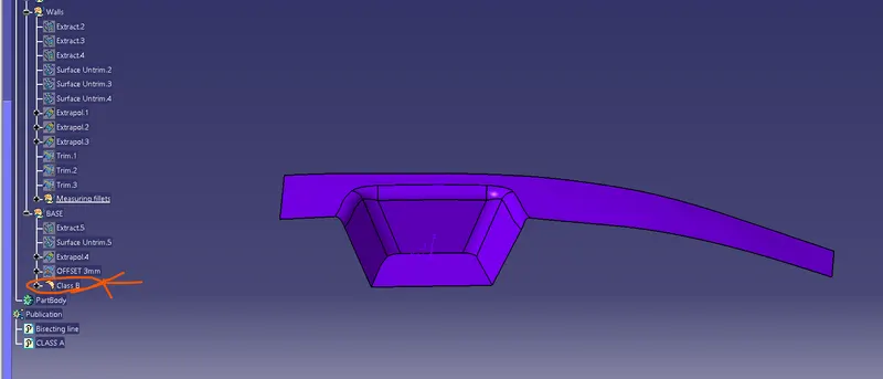
Class B surface is created by extracting each wall and untrimmed walls extrapolating the walls and then trimming the extra surfaces and
offsetting it to certain value based upon the thickness of the component where it is 2.5 mm. The offset surface will be the B-Surface
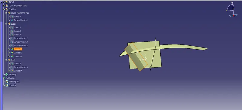
If Measurements are not proper for the fillets select the region which requires and untrim to measure the exact dimentions.
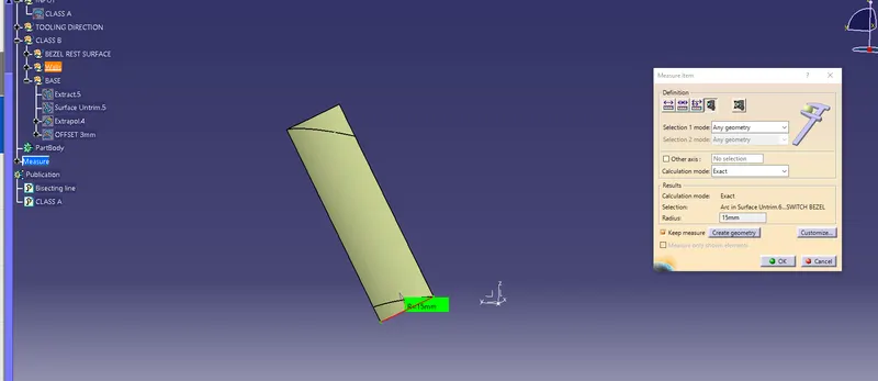
Checking and confirming weather it is 3deg Thickness or not.
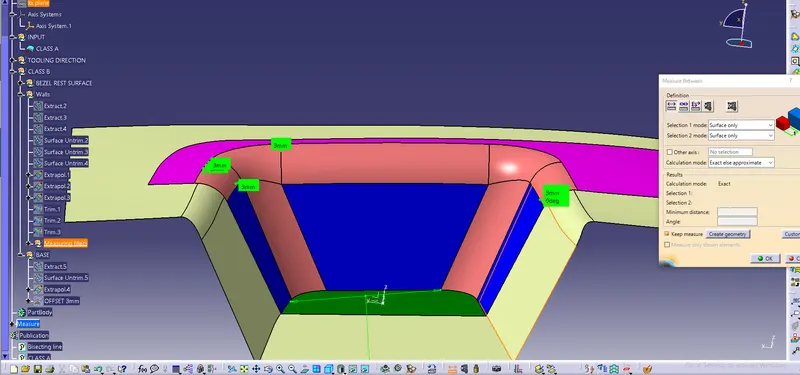
Class B
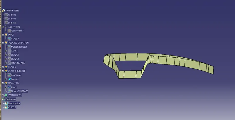
CLASS C SURFACE:
This surface is obtained by sweeping the boundaries of the Class A surface along the Tooling axis direction, It connects both A and B surfaces.
The Final trim part is converted into a solid component using closed surface coomand in part workbench.
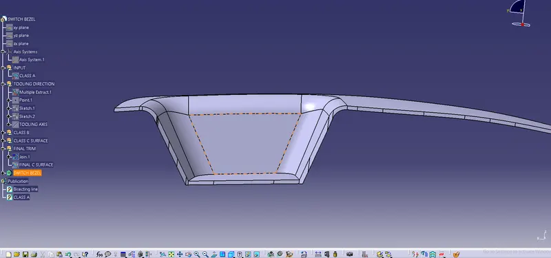
Draft Analysis of closed Surface model: