Using Morph for the given Sheet Metal Using ANSA
Aim:
The Main Objective is to use different Morphing Techniques of the given Model.
Methodology:
The Steps followed to do a proper morph is as follows:
- Checking the Geometry.
- Giving the PID.
- Morphing the Model.
Theory:
- Morphing:
ANSA encompasses a full-fledged Morphing menu which is completely integrated with ANSA’s interface and doesn’t require any additional module installations or licenses. The functions of the Morphing menu can be used to efficiently re-shape both FE and/or Geometry based models.
- Domain (Box) Morphing:
Domain or Box Morphing is preformed via boxes that are created around a particular part or assembly that the user intends to morph. The movement of the Morphing boxes control points defines the morphing operations on the entities inside the Morph box. This type of Morphing can be applied to both FE and Geometry based models.
- Direct Morphing:
ANSA’s Direct morphing features gives the user the ability to efficiently modify a part locally without having to create Morphing boxes. This method is extremely useful in creating local modifications on single parts. Creation of depressions, surface fitting certain FE part features to new target geometry, moving selected features along the contour of a surface, and also the ability to freeze (rigid) elements during the morphing process are some of the direct morphing abilities.
- Parametric Morphing:
The desired morphing actions can be saved as parameters that can be accessed in batch mode. Users can enforce desired shape changes by changing the numerical input value for the appropriate parameter. This method of morphing is highly utilized for the coupling of the morphing operations to an external optimizer. The scripting capability can be used in conjunction with ANSA’s parametric morphing functionality to deliver faster DOE models.
- Geometry Morphing:
ANSA brings to the CAE world it's one of a kind tool for CAD geometry morphing. This pioneering concept allows the user to utilize the inventory of all the familiar FE morphing functions to perform equivalent operations in a CAD environment on geometric entities.
Procedure:
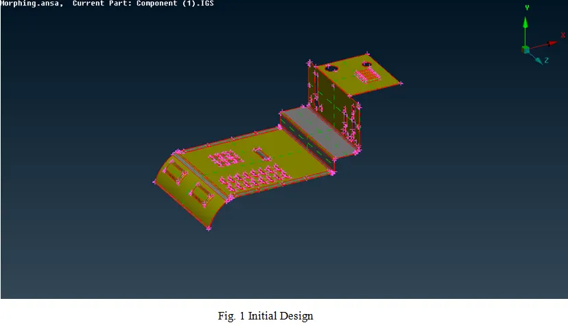
- Opening the File and Geometric Clean-up:
- The file is downloaded initially. To open the file, follow the steps.
Open ANSA >> Give Command Arguments >> OK >> Click Ctrl +O (for opening the file) >> Select the File>> Click Ok. - This process is just used to check the topology of the model.
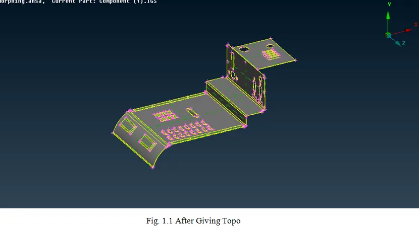
- In order to check the Topology follow the process as Tools>> Checks >> Geometry>> Execute.
- Once executed, it might show a green bar stating there are no errors in the geometry or it may show the dialog box showing the errors present in it.
- These errors can be fixed either by going on with them individually or once Right-clicked on the mouse an additional list pops- up.
- Fix option will be present in that pop-up when it is clicked the errors which can be fixed are executed and it might contain only a few errors which should be fixed manually and if no errors are present then it will show the green bar stating executed.
- The process is called geometric clean- up. It can be done either completely or part-wise of the parent geometry.
- Giving the PID:
- The PID is used to create a property of the particular model parts or the total model. In order to create a new PID or to check the existing PID’s. Click Lists >> Properties.
- You can see the Properties which are created before. In order to create a new PID, right-click on the dialog box, the drop-down appears. Click New >> PSHELL>> PSHELL.
- Then a New PID is created. In order to assign a part to the PID. Select the element needed to be assigned and do the middle click on the mouse to confirm.
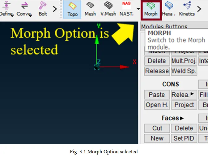
- Morphing the Model:
- Morphing is used to change the shape of the model.
- Initially, the morph is needed to be created. To create a New Box Morph Click Morph Deck, In Boxes module >> Click New >> Ortho >> Select Geometry and Box Type as Ortho >> Select the Entity >> Click OK
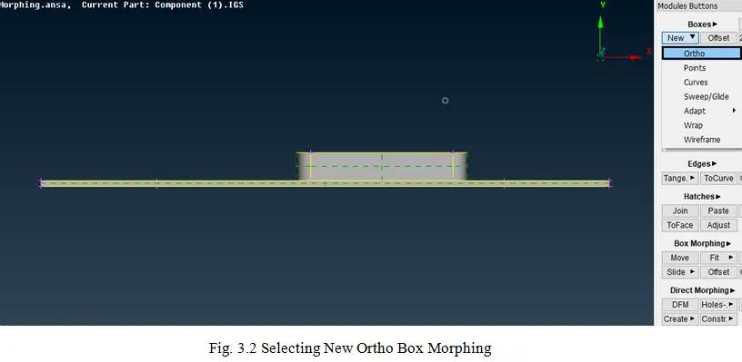
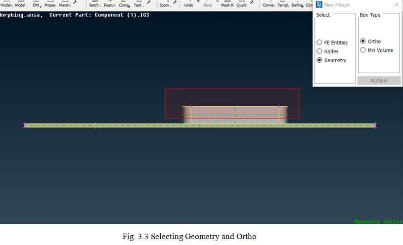
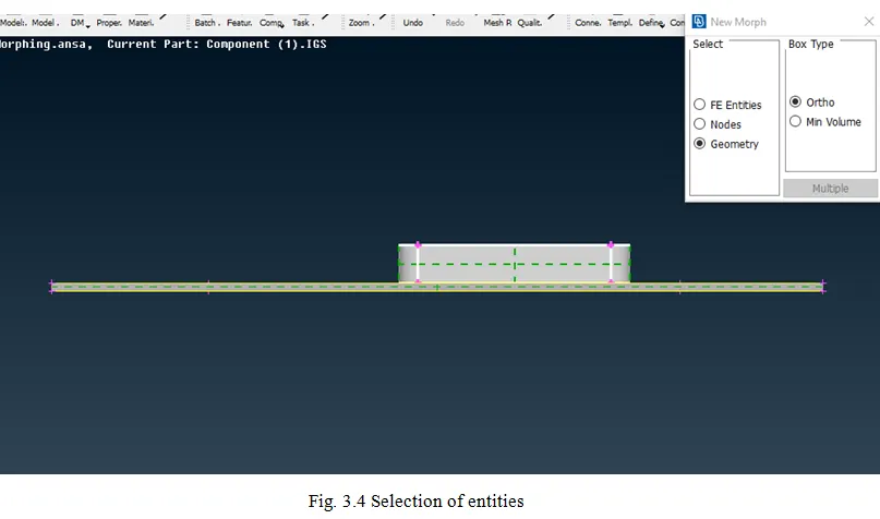
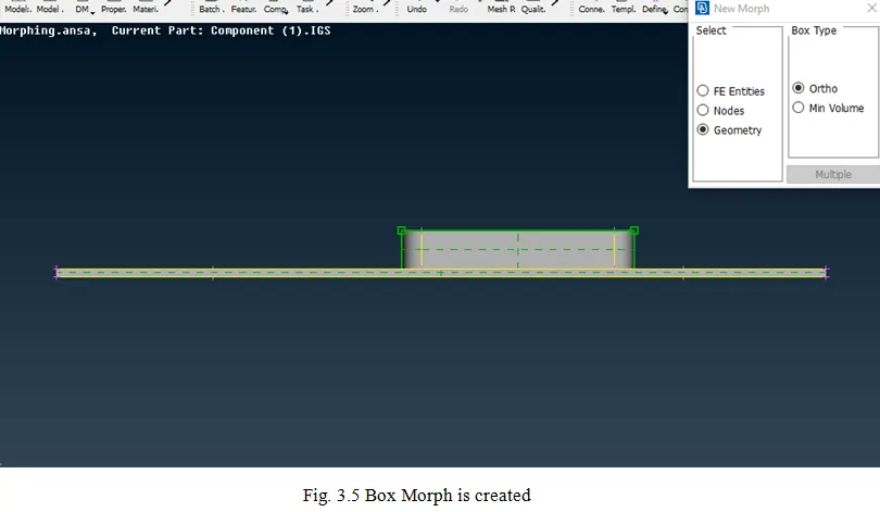
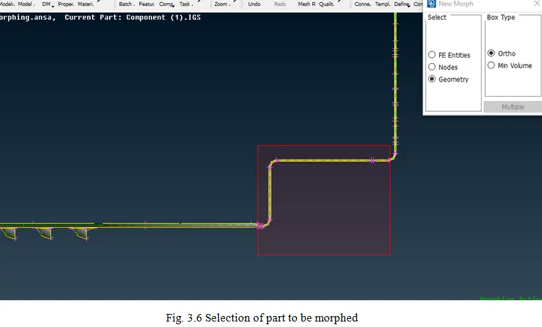
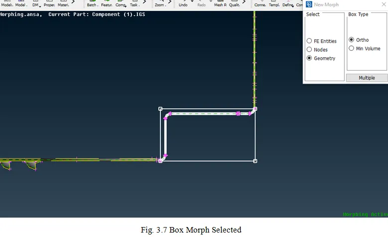
- The New Box Morph is created.
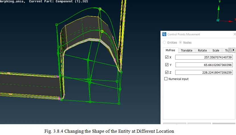
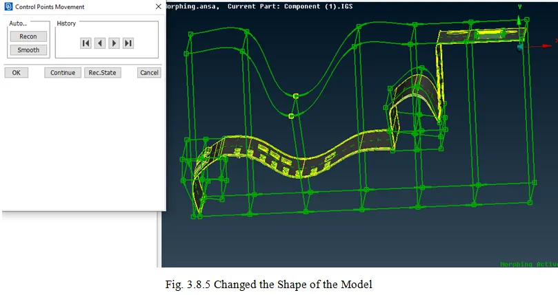
- The Created Morph on which the Morphing needs to be done has to be move or in literal terms, the shape needs to be changed either by the given dimensions or rather normally.
- To move the box model, In Box Morphing, Click Move >> Select the Edge nodes on the box >> Move the model (That is to change the Shape) >> Click OK
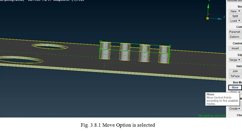
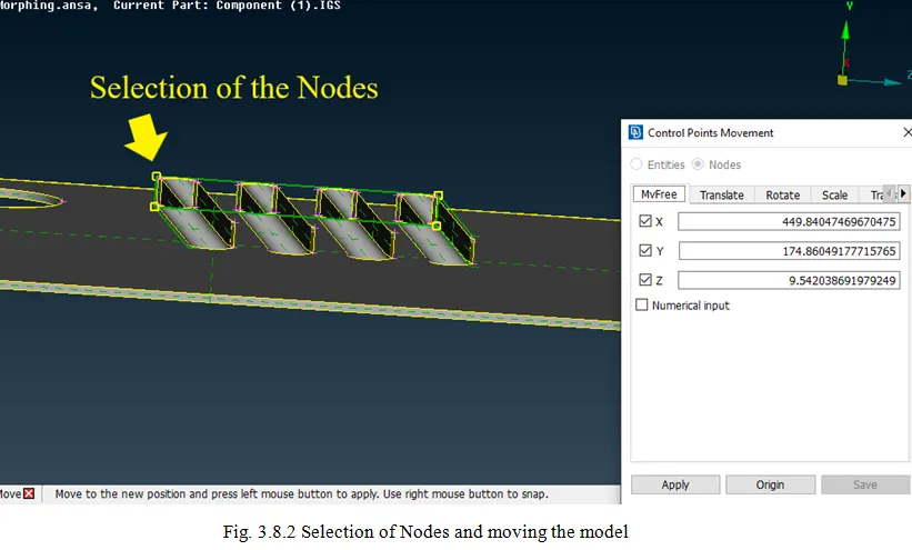
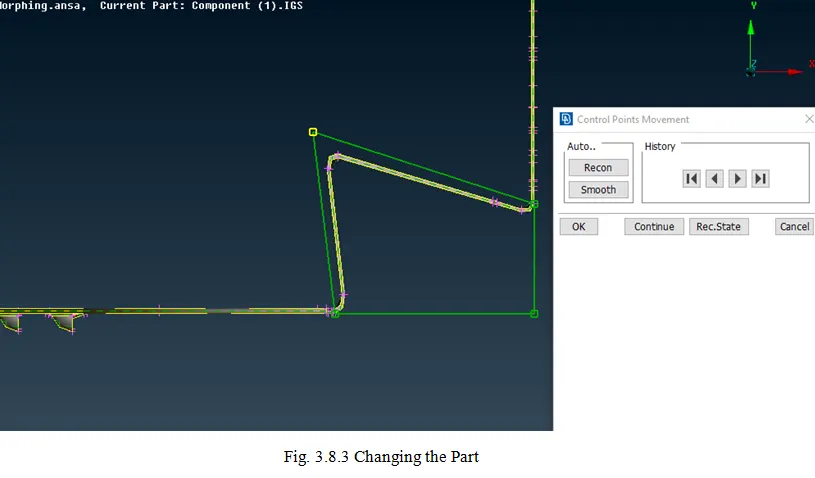
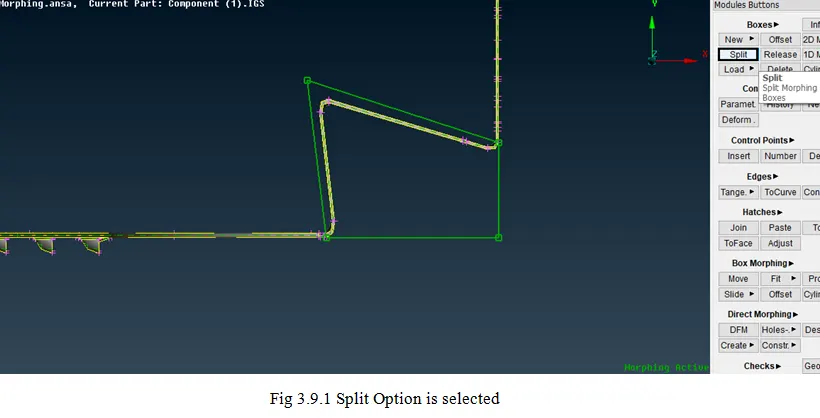
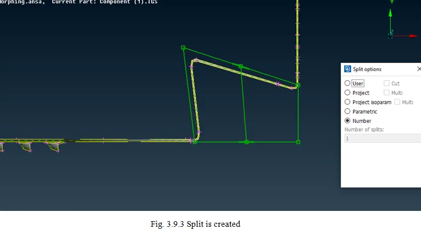
- If the Selected Box is created in one shot, the Box can be split into as many parts as the user needs.
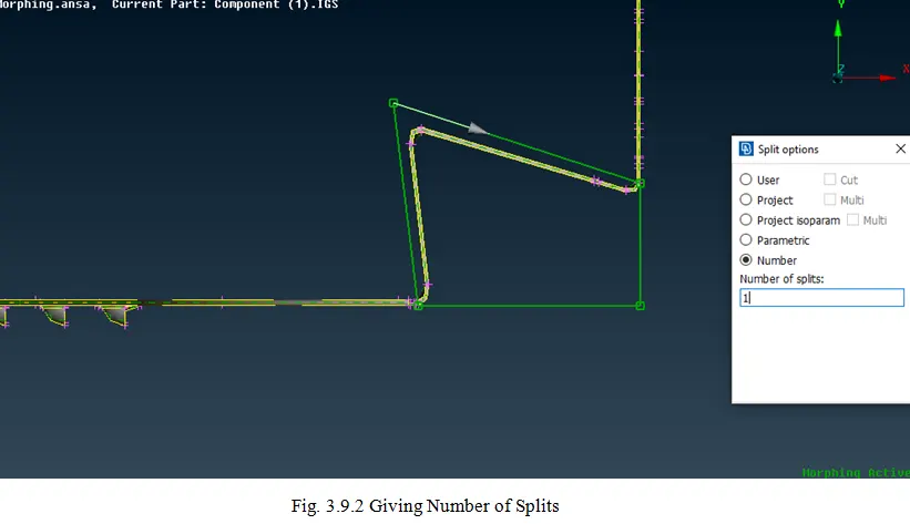
- In Boxes Modules >> Click Split >> Click Number >> Select an Edge >> Give Number of Splits >> Click OK.
- The Number split creates the Number of splits within the box equally.
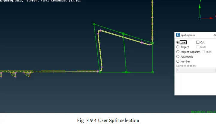
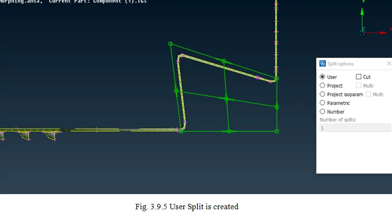
- In Boxes modules >> Click Split >> Click User >> select an Edge >> Click OK.
- In the above process, the user can create a split at any location, the user selects.
Errors:
- The errors faced while doing the morphing is the De-featuring of the CAD model.
- This De-featuring is general just the CAD error which can’t be changed normally and when tried to change it using the Normal Cut and New Faces option the faces doesn’t get formed normally they just create a line.
Results:
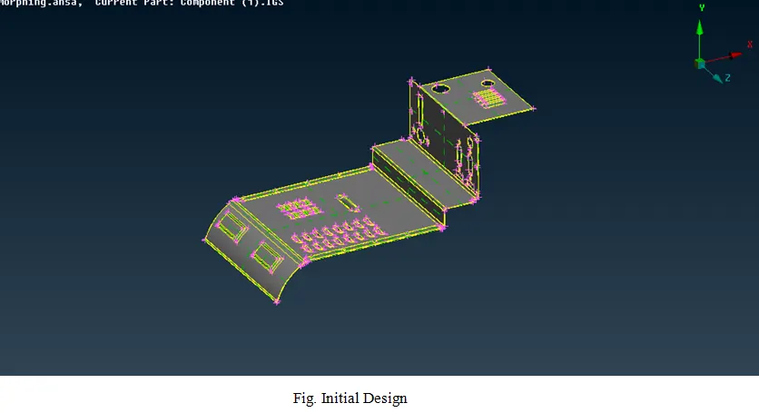
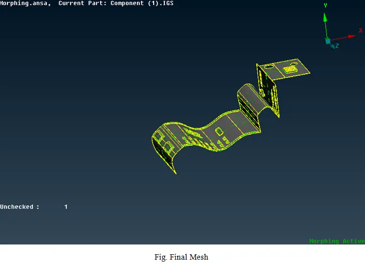
The Morphing techniques are created in the given model.
Learning Outcomes:
The Key aspects learned while performing the mesh.
- Learned about Morphing
- Creating of the Box Morph
- Generating the Split Box
- Moving/changing the shape of the Model.
Links Used:
Morphing: Details of Morphing
Google Drive Link: Morphing Completed