Week 7 State of charge estimation
1. TEST CASE 1
Test Harness Dahboard
Plot
Analysis
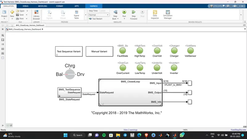
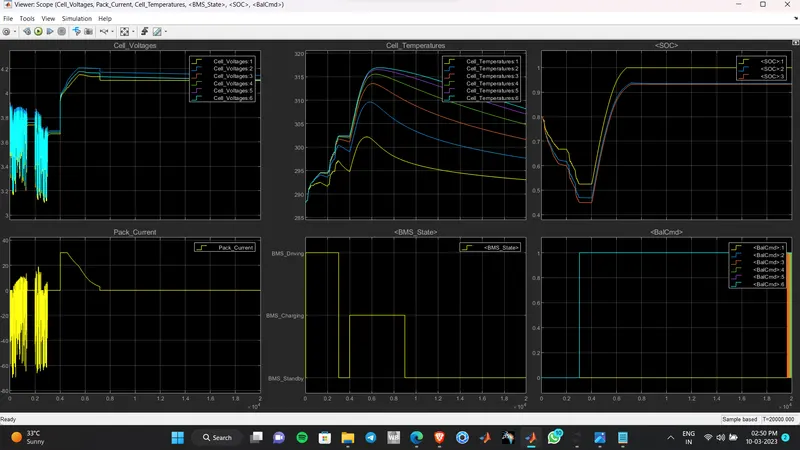
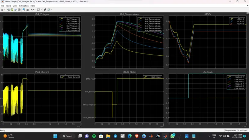
The dashboard blocks are green, so no fault state detected. When we analyse the plot we can see, initially the BMS was in driving mode, The voltage plot shows that it is reducing wit time.The pack current plot says it is discharging and regenarative braking is charging the battery as well. The cell temperature is rising while discarging . The cells with higher temperature will be positioned at the centre of battery pack Charging happens between 0.4 and 0.9 s(10^4 ) .Initially it was constant current charging and then constant voltage charging. So when we observe the SOC plot from time 0.4 to 0.5 SOC increased linearly,so very quickly because of constant current charging but from 0.5 to 0.9 it was rising littile bit exponentially ,so it took time , beacause of constant voltage charging. Cell balacing happends at charging and standby mode . After charging the BMS settles in standby mode. The current drops to zero, the temperature reduces , soc remains constant over time
CASE 2
PLOT
Analysis
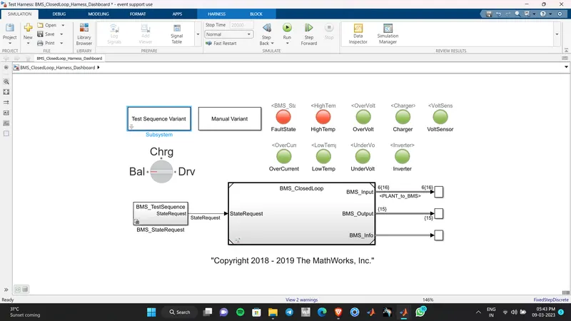
The dashboard Indicates a High temperature fault state .Initially the BMS was in driving, so voltage and pack current, SOC was reducing and temperature was rising , end at t=0.5 s (10^4) .Then BMS came to charging the SOC was rising, cell balancing happends. But when time t= 0.62 s (10^4), The BMS fault condition is achieved then the BMS has disconnected the charger ,thus the current drops to zero, SOC remains constant, temperature reduces over time
CASE 3
PLOT
Analysis
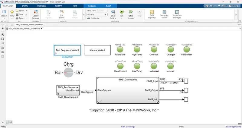
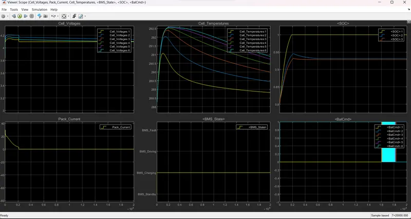
Dashboard indiactes there is no fault in the simulation. The BMS is in a charging mode over the entire time according to the algorithm. Pack voltage attains its maximum value, Due to cell balancing the voltage reduced. Battery attained 100% SOC very quickly compared to other simulation, so it disconnected the charger, then current drops to zero,temperature reduces , SOC and voltage remains constant over time
2.COULOMB COUNTING METHOD
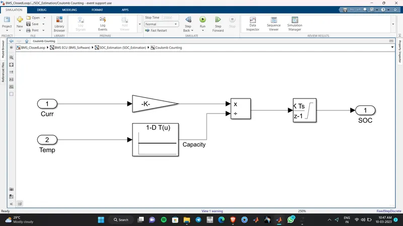
This method works by Integration of current over time using a discrete time integrator block along with a temperature
in consideration. This method has less accuracy compared to UKF and EKF