Week 7 State of charge estimation
1.1st Test Case : Driving,Standby and Charging.
Analysing the plot and we can explain.
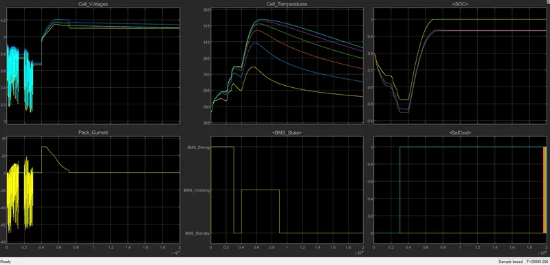
in the first graph it is the voltage changes related to the three events,from the graph we can observe that during driving the voltage is varying in accordance with the load we are giving upto 3000 seconds and from 3000s to 4000s we can able to see the stand by mode in which the voltage is constant because there is no load and after that the last we are charging the system in which it is clearly visble that the voltage is incresed the to the rated voltage and then it is maintaining a constant voltage output.if we discussed about the pack current it is same like voltage because we know that voltage and current is directly proportional.so both have same characteristics some small variation in the driving.
when we considered about the Cell Temperature in the initial it started with a less temperature and then it is raised to a higher value and in the standby mode a slight decrease in the cell temperature because of no load and when it is connected to charger or in charging mode the cell temperature raises to a maximum value and then gradually decreasing.
in BMS graph we know there is three steps followed by this process Driving,standby and charging.and for SOC we know that while driving the SOC will drop and when in standby mode it will remains the same and atlast the charging ,in which the SOC will increase and after acheiving the 100 percent it will go for cell balancing.
2.2 nd Test Case : Fault Condition
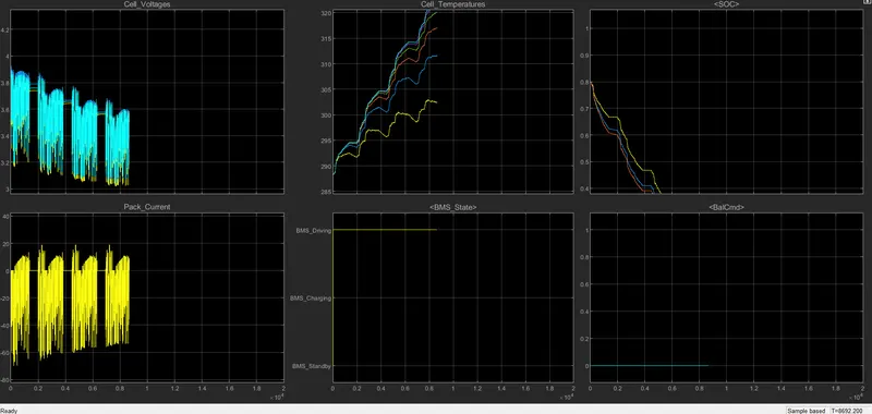
in here we understand the faulty condition occurs due to the immense change in the Cell Temperature,in the graph it is clearly visible that the temperature is going beyond the limited value so in here both voltage is varying and comes to zero in here we have only the charging phase but the teperature is very high so as per the fault the SOC also went to zero.in here we know there are different cells and all cells have different temperature but it will affect our system very badly.
3. 3 rd stage : Charging State
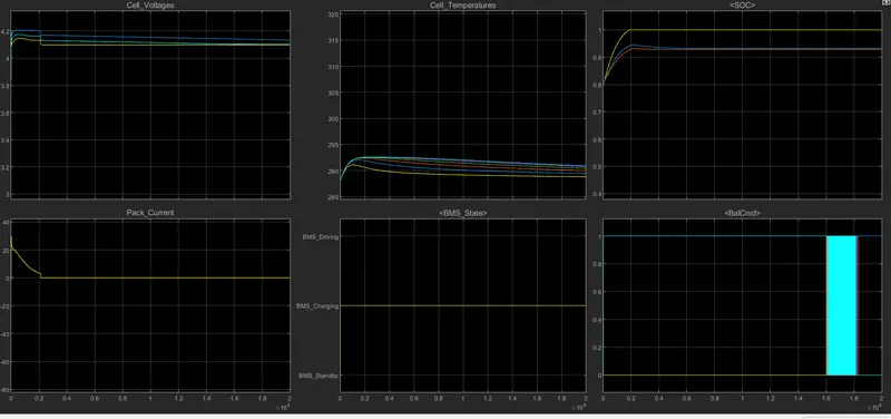
in charging state we understood that the cell voltage are in a constant state and also for the pack there is no any change ,sudden there is a decrease from there it isa constant value and in the case of cell temperature there is a sudden small gain and then it is almost constant, in the case of SOC also have the same criteria.and for BMS it is showing the charging state only.
2.Coulomb counting
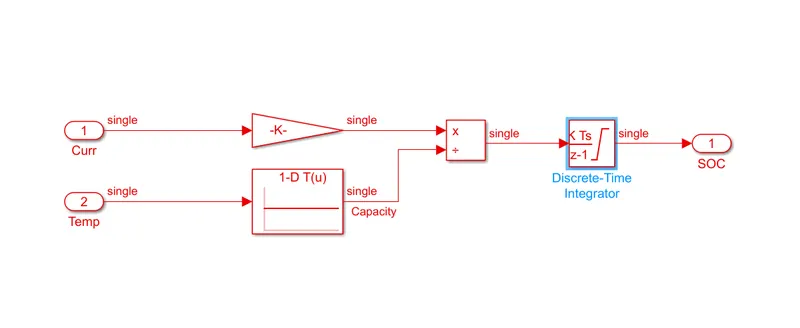
We are using the Coulomb counting is for the SOC estimation ,in which we are having two inputs one is current capacity in Ah and Temperature.and then the current is converted to seconds by using the gain block and we are getting is by means of dividing the current with the temperature.and also we are using Discrete Time integrator by functional,actually in here we are changing the mathematical formulae into simulink model and thus we are plotting the SOC.in here all this process are done by BMS.