Week 7 State of charge estimation
1.Simulate the 3 test cases from harness dashboard and write a detailed report on the results.
Ans.
Design and Test Lithium Ion Battery Management Algorithms:
Model:
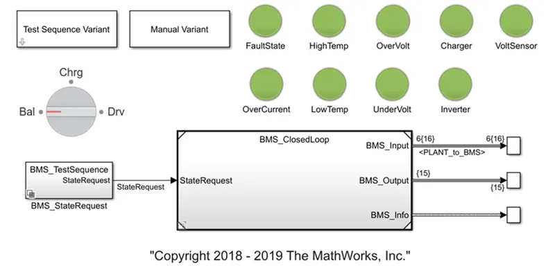
The above figure shows the BMS_ClosedLoop_Harness_Dashboard for design and test lithium ion battery management algorithms. This model consists of charge discharge current limiter, state machine which decides BMS states, SOC estimation, Passive Cell balancing logic, Battery pack, Precharge circuit, Charger and Load. Also It is designed for some pack, charger and inverter test.
In this model two types of battery pack are used one is 6 cells in series and another is 16 series module which consist of 6 series connected cells i.e. 96 cells. Also in this SOC estimate in three ways: coulomb counting, Unscented Kalman Filter and Extended Kalman Filter.
This model we can simulate in three test sequence modes.
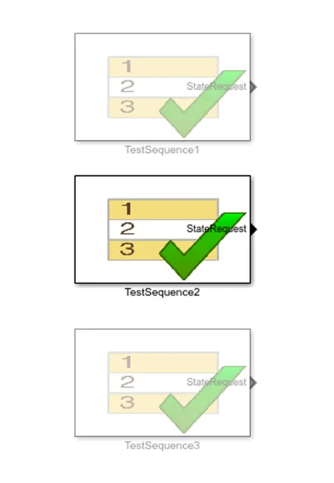
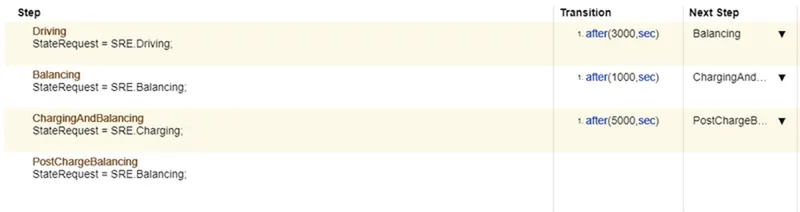
In the first test sequence model, BMS drive for 3000 sec after that 1000 sec BMS get standby or balancing and then for 5000 sec pack charge and remaining time again BMS get standby position.
In the second test sequence model, BMS drives for 10000 sec only.

In the third test sequence model, BMS charge the battery pack for all time.

Now, BMS algorithms model simulate with preset simulation time for 6 series connected cells. Test sequence varies by changing the test sequence variant parameters.
Test 1 Result:
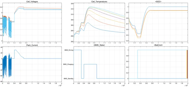
- The above figure shows the various plots of battery pack and BMS parameters. The BMS state plot shows the BMS status like Driving, Charging and Standby condition which is similar to mention in test sequence modes.
- If we see the current and voltage of the battery pack when BMS driving, they significantly fluctuate due to the driving patterns of vehicles.
- BMS driving mode battery pack current is negative because current gets out from the battery pack and sometimes it's positive because of the regenerative braking.
- At the same time cell temperature is increasing and SOC is slightly decreasing.
- When BMS is in standby mode for 1000 sec pack voltage, current and SOC is stable and cell temperature is decreasing.
- At the starting of standby mode cell balancing logic gives command for cell balancing because in this model passive cell balancing technique is used and we can not operate passive cell balancing during the discharging.
- At 4000 sec BMS starts charging the battery pack for 5000 sec. If we observe the current and voltage plot then we get the idea about battery pack charge with CCCV technique.
- When constant current charging starts, temperature starts increasing and after that when constant voltage charging starts temperature starts decreasing.
- Similarly in constant current charge SOC increases rapidly and when constant voltage charging starts SOC increases slowly. After completing the full charge of the battery pack, all parameters get stable.
Test 2 Result:
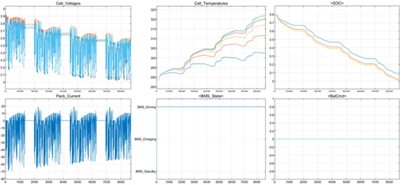
- In this test BMS operates only in driving mode for 10000 sec. Therefore there is no cell balancing command.
- This result is similar to the starting 3000 sec result of test 1. The Current and voltage fluctuates as per drive patterns of vehicles.
- During this test cell temperature is increased and SOC decreased.
Test 3 Result:
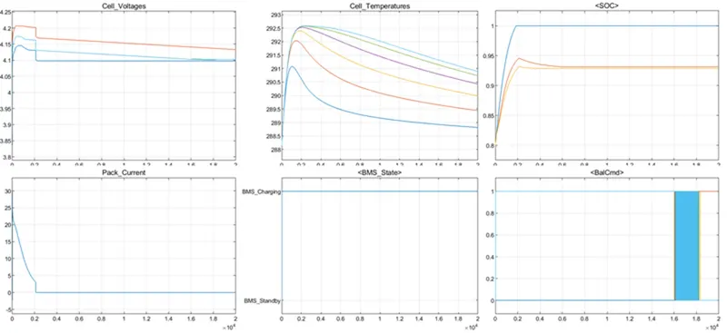
- In this test BMS only charge the battery pack for the whole simulation duration. Therefore cell balancing logic gives the cell balance command at the starting of the simulation because we can operate a passive cell balancing technique during charging.
- In this test also the battery pack charge with CCCV technique. We can see in the temperature plot when constant current charge is happening at that time cell temperature is increased and as constant voltage current starts, temperature starts decreasing.
- After full charge of the battery pack, cell voltage starts stabilizing at maximum voltage, current reduces to zero and temperature starts reducing upto ambient temperature.
Conclusion:
- SOC estimate by using coulomb counting is slightly higher than the other two methods and Unscented Kalman Filter, Extended Kalman Filter calculate the similar SOC.
- It happens because coulomb counting calculates ideally or mathematically input or output goes charge from the battery and In the case of Kalman filter it considers various effects and calculates practical SOC.
- During the BMS driving mode or at discharging the battery pack, passive cell balancing is not possible.
- During the constant voltage, temperature of the cell gradually reduces because at the same time charging current also gets reduced.
What is coulomb counting? Refer to the above model and explain how BMS implements coulomb counting for SOC estimation?
Ans.
Coulomb Counting:
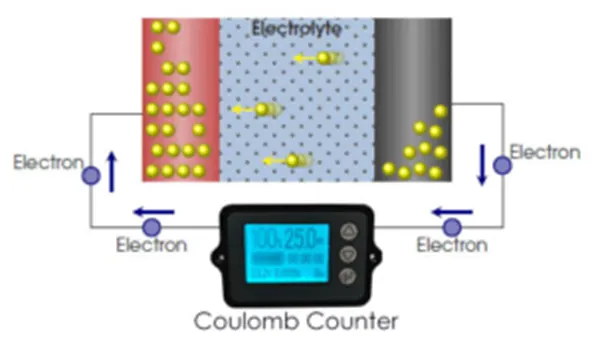
Coulomb counting is a technique used to track the State of Charge (SOC) of a battery pack. It works by integrating the active flowing current (measured in amps) over time to derive the total sum of energy entering or leaving the battery pack. This produces a capacity that is typically measured in Ah. It means in coulomb counting measuring the current (total charge in coulomb) flowing in and out of the battery. For this technique SOH is required. If SOH is not accurate then SOC accuracy also decreases.
Change in SOC = Charge pumped in or out of battery / (Total capacity * SOH)
SOC (new) = SOC (old) + Change in SOC
Charge (Q) = Current(I) * Time(t)
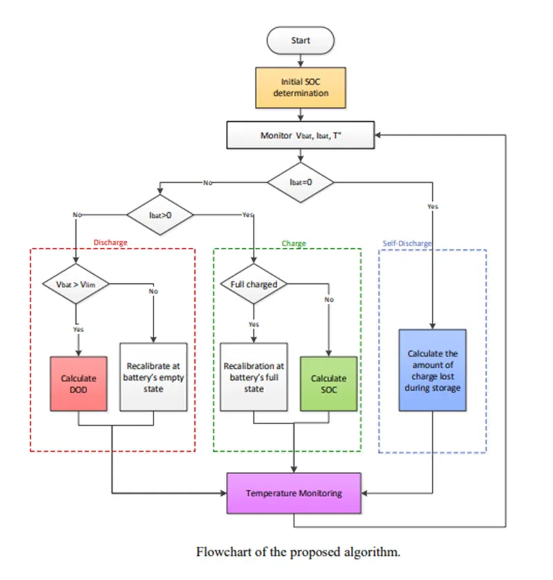
Flowchart for Algorithm of Coulomb Counting:
Coulomb Counting Subsystem Model:
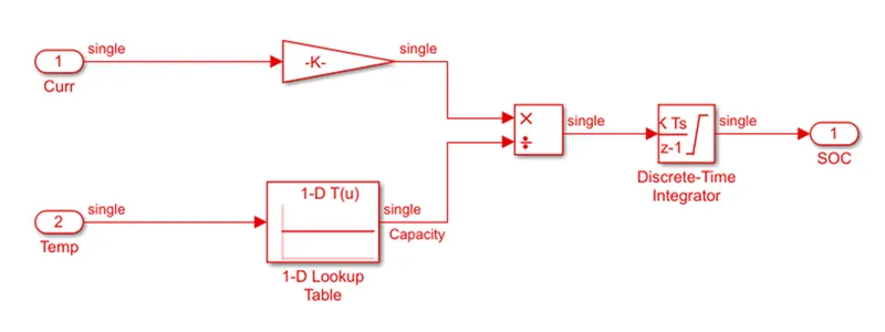
The above figure shows the coulomb counting subsystem and it works as we discussed earlier. Battery pack current and cell temperature signals are used as an input and the SOC is an output signal. Discrete time integrator used for converting current into the charge with respect to time. Gain block used for the converting time in sec to hour i.e. gain value is 1/3600. Use a 1-D lookup table for predicting total capacity while considering cell temperature. In 1-D lookup table breakpoints are cell temperature and table data is battery capacity.