Week 7 State of charge estimation
Design and Test Lithium Ion Battery Management Algorithms
Using the link: https://in.mathworks.com/matlabcentral/fileexchange/72865-design-and-test-lithium-ion-battery-management-algorithms
BMS(Battery Management System):
- A Battery Management System (BMS) is an intelligent component of a battery pack responsible for advanced monitoring and management. It is the brain behind the battery and plays a critical role in its levels of safety, performance, charge rates, and longevity.
- Our BMS is designed to be a long-term solution for our customers with the highest level of safety in mind. Advanced algorithms and electronics ensure high precision measurements:
BMS Provides:
- Monitoring the battery
- Providing battery protection
- Estimating the battery’s operational state
- Continually optimizing battery performance
- Reporting operational status to external devices
The battery management system works
Battery management systems do not have a fixed or unique set of criteria that must be adopted. The technology design scope and implemented features generally correlate with:
- The costs, complexity, and size of the battery pack
- Application of the battery and any safety, lifespan, and warranty concerns
- Certification requirements from various government regulations where costs and penalties are paramount if inadequate functional safety measures are in place
There are many BMS design features, with battery pack protection management and capacity management being two essential features. We’ll discuss how these two features work here. Battery pack protection management has two key arenas: electrical protection, which implies not allowing the battery to be damaged via usage outside its SOA, and thermal protection, which involves passive and/or active temperature control to maintain or bring the pack into its SOA.
As per the Simulink, here we can modeling the and simulation capabilities enable BMS development including single cell equivalent circuit, Control design, Power electronics, Code generation, and verification.
- Modeling battery packs using electrical networks whose topology mirrors that of the actual system and scales with the number of cells
- Parameterizing equivalent circuit elements using test data for accurate representation of cell chemistry
- Designing the Power electronics circuit that connects the pack with the controls
- Developing closed-loop control algorithms for supervisory and fault detection logic
- Designing state observers for state-of-charge and state-of-health online estimation
Using Simulink, engineers can exercise the battery management system over a range of operating and fault conditions before committing to hardware testing.
Model:
Lithium Ion Battery Management System Algorithm Design and Test:
This example project can be used as a reference design to get started with designing Lithium Ion Battery Management System (BMS) with MATLAB and Simulink.
Project includes Simulink models for BMS Algorithms such as:
- State of Charge estimation using Extended Kalman Filter, Unscented Kalman Filter
2. Passive Battery Cell Balancing
3. State Machine for Pre-charging and Contactor Management
4. Fault Management - Over/Under Voltage, Over Current, Over Temperature etc.
5. Charge and Discharge Current Limit Calculations
To design and test these algorithms, project also includes files for
1. Li-ion Battery Cell Parameter Estimation
2. Battery Pack with 6 cells in series and 96 cells in series
3. Simulink Test files with test cases to test State Machine Logic
4. Linking requirements to Models
BMS Model:
BMS ECU means Battery Management System with Electrical Circuit Unit and a Plant. The control unit has various monitoring and control algorithm is connected to a block with a representation of battery pack and an associated battery circuit.
This is a two version battery pack 6cell in series and a16 module pack.
The Architecture is 6S1P & 96S1P Pack.
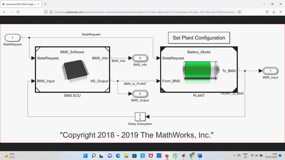
BMS ECU Subblock:
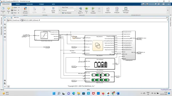
The BMS ECU includes one state machine and cell balancing block. This is represents current power of the cell.
The state machine defines the main operating state of the BMS.
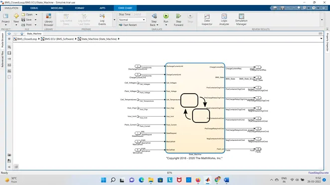
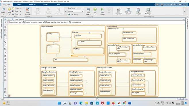
- The first one defines the variables BMS_State which indicates standby , driving, Charging, and fault. Charging comprises constant & Constant voltage.
- The second state switches the fault state ON in case Current, Voltage, or Temperature reaches an unsafe levels.
- The 3rd &4th states are defined the Charger & Inverter. This is needed for excessively large current at the beginning of the Charging state.
- Plant Block:
-
Plant is mainly Battery. That is connected to Charger & Load, In Charger and Load there is Motor through the inverter connected through wires and charger also connected through wires. Charger load is forming a subsystem. They are connected in parallal configuration.
1 . Charger connection & 2. Inverter Connection.
In inverter we put DC driver load to run the Inverter. This is created virtually current draw based on driving cycle block 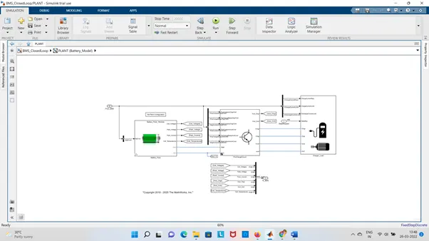
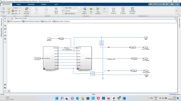
- Individual cells:
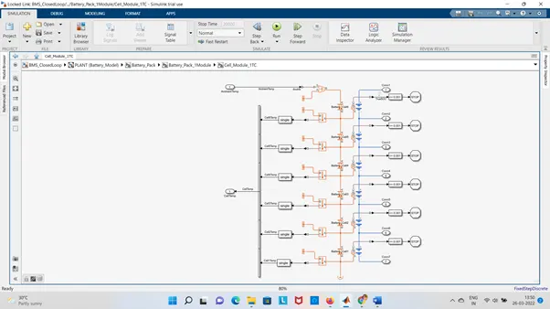
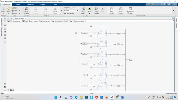
-
This module includes the Battery Pack (One module 6cells in series and 2.16 modules with 96 cells .Battery pack is connected to charger and connector.
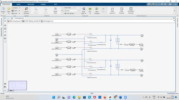
Pre Charge Circuit: Pre charge circuit is required to ensure that sudden rush of current. Here we can find two resistor connected together. May be the direction of the current is reverse. There are pre charge Relay command which is operated the circuit. Positive & Negative main wires are there. Positive is connected to pre charge circuit and positive & negative charger is connected below which is connected to the inverter positive.
-
Closed Loop Simulation with Algorithm:
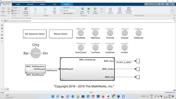
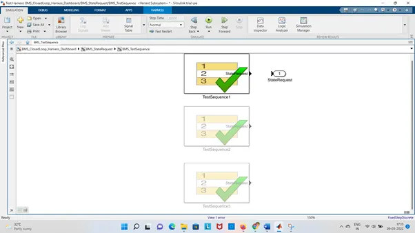
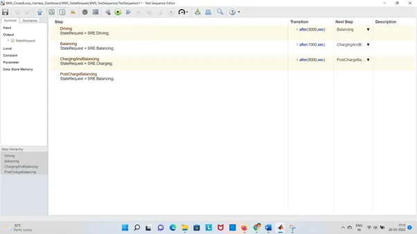
Here three different test cases shown. This dashboard will help us to understand the 9 different states (Error) from three different states (Driving, Charging & Stand By). like Fault state, High Temp, Over Volt, Charger, Volt Sensor, Over Current, Low Temp, Under Volt, Inverter.
Battery Management System are implemented state machine diagram.
The above diagram is helps us to understand the present situation in drive cycle.
If the LED s are represents green colour then there is no fault and if the LEDs are represents red then there is a fault.
We can see the BMS status also.
Whether it is driving or discharging through inverter or charging through charger or balancing
-
Here three different test cases shown. This dashboard will help us to understand the 9 different states (Error) from three different states (Driving, Charging & Stand By). like Fault state, High Temp, Over Volt, Charger, Volt Sensor, Over Current, Low Temp, Under Volt, Inverter.
Battery Management System are implemented state machine diagram.
The above diagram is helps us to understand the present situation in drive cycle.
If the LED s are represents green colour then there is no fault and if the LEDs are represents red then there is a fault.
We can see the BMS status also.
Whether it is driving or discharging through inverter or charging through charger or balancing
-
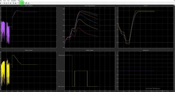
The scope is resulting various conditions. State of Charge is 90% means it is stand by mode. The battery pack voltage is increases to 4 when it is charging. After the driving cycle SOC is below 50% and shifted to charging mode until it reaches 100% . The supply of current is shown here in the above plotting.
- What is coulomb counting? Refer to the above model and explain how BMS implements coulomb counting for SOC estimation ?
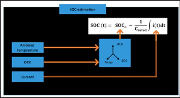
Coulomb counting is a technique used to track the State of Charge of a battery pack. It works by integrating the active flowing current (measured in amps) over time to derive the total sum of energy entering or leaving the battery pack. This produces a capacity that is typically measured in Amp-hours.
-
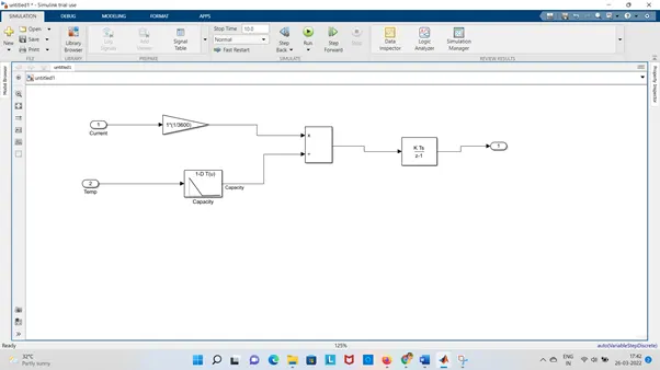
To determine the available capacity , coulomb counting relies on the integration of current drawn from the supplied battery over time.
SOC (t) = SOC(t0) -
Where I is the current and η is the efficiency during charge and discharge operations.
Advantage of CC : Accurately estimates battery SOC by Coulomb Counting .Battery capacity & efficiency are significantly influenced by operating of Temperature & current . Even though the method is not suitable for real-time SOC estimation.
But Since the coulomb counter is an open loop estimator, errors in the current sensor is added by the estimator. The cumulative error becomes larger, when the SOC estimator operates through a longer time period. Also, an incorrect result can be generated faster, when the current sensor has massive errors. When the battery ages in real time, the battery capacity varies, but the coulomb counter cannot detect or take measures for the issue. As a result, SOC estimation will not be accurate, if the real pattern of the battery estimation deviates from the expected pattern. The initial SOC should be measured by the terminal voltage of the battery pack. So any error contained in the initial estimation method will be carried throughout the process and this method cannot detect or repair the initial error
- The Coulomb Counting method can be improved by considering the Coulombic efficiency (ηAh) at different temperature and charge rates. It is defined as the ratio between the number of charges extracted during the discharging process and the number of charges enter during the charging process or the ratio of the discharging capacity to the charging capacity (given by the below equation). ηAh = Qdischarge Qcharge × 100% Since ηAh depends on the current rate (discharge or charge) as
mentioned above, an Equivalent Coulombic Efficiency (ECE) (ηeq) is developed including the discharge and charge Coulombic Efficiency.
discharging capacity to the charging capacity ηAh = Qdischarge Qcharge × 100%
SOC Estimation:
-
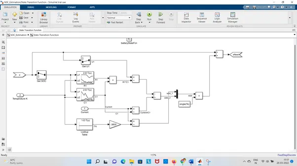
The pack current is converted to Ampere Hour dividing by 1/3600 and then diving by the rated capacity (using 1D Look up table) and integrating that value with an discrete time integrator. To provide the SOC estimation through the simulation.