Week 7 State of charge estimation
Q1.Simulate the 3 test cases from harness dashboard and write a detailed report on the results
ANS:-
Lithium-ion battery packs are the widely used energy storage systems in electric vehicles. The battery management system (BMS) is responsible for safe operation, performance, and battery life under diverse charge-discharge and environmental conditions. When designing a BMS the cell voltage and temperature, state of charge, state of health and the charging profile has to be controlled and maintained.
Also, it indicates whether there has been a fault, for example that any cell has reached an over-temperature condition or under-voltage condition (Under-voltage occurs when the average voltage of a system drops below intended levels. It is usually caused by undersized or overloaded utility).
AS PER GIVEN PROCESURE BMS MODEL IS SUCCESSFULLY INSTALLED IN MATLAB
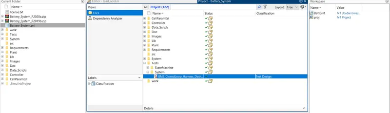
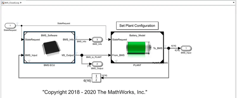
NOW SIMULATING THE CLOSED LOOP HARNESS DASHBOARD SIMULINK MODEL:-
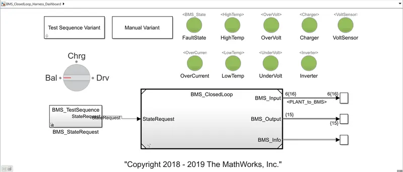
The harness dashboard is shown below.
It consists of the test sequence variant subsystem which holda three different test cases.
This dashboard also helps in determing the fault states and other parameters as shown in the diagram below.
Green color indicates that the system is working without any errors while red signal will indicate that there is a fault in the system
THERE ARE THREE TEST CASE LISTED BELOW:-
a.) The first one defines the variable BMS_State which indicates standby, driving, charging, and fault. Charging comprises constant current and constant voltage stages.
b.) The second state switches the fault state ON in case a current, voltage, or temperature value reaches an unsafe level.
c.) The third and fourth states define the contactor ON and OFF switching sequence for the charger and inverter. This is needed to avoid an excessively large current inrush at the beginning of the charging stage.
CLOSED LOOP HARNESS DASHBOARD SIMULINK MODEL.:-
NOW MODEL IS RUNNING IN THE DOCUMENT SECTION TO AVOID THE ERRORS:-
1. TEST CASE 1:-
There are three stages of driving condition, namely-
- Driving
- Charging
- Standby
When the simulation begins, initially the vehicle is in driving state and the SOC will decrease for this time period. After a time period of 3000 seconds the next step is balancing mode and the vehicle is in standby condition. After, another 1000 seconds, the vehicle is in charging phase and the battery's SOC increases almost to 100%. The next phase is the postcharging phase in which the vehicle again goes for the standby mode.
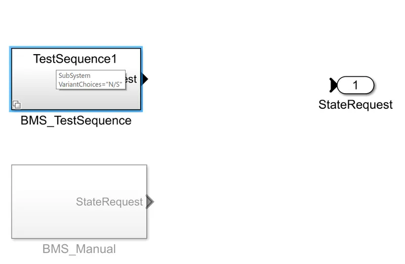
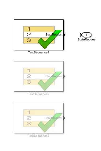
different steps are as below driving, balancing, charging, standby

RESULT SCCOPE
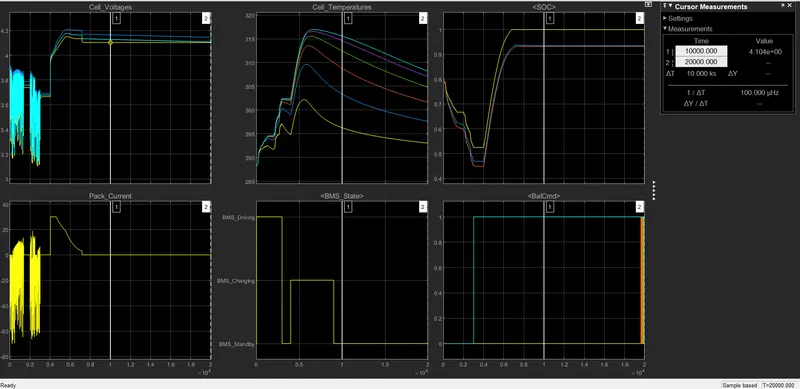
From the scope results we can define note the following points.
- The input cycle can be seen in the BMS_State plot in which the vehicle initially undergoes driving, then charging till SOC= 90% and then later in standby state.
- During Charging the Battery pack voltage is increased upto 4.2V.
- The cell temperature increases during the driving and charging cycle and starts falling off in standby mode.
- The SOC drops to less than 50% after the driving cycle and then later put into charging until SOC Reaches 100%.
- The Current supplied to the EV during driving phase can be seen in the current plot.
2. TEST CASE 2:-
SIMPLY CHANGING TEST CASE FROM THE TEST SEQUENCE VARIENT SUBSYSTEM
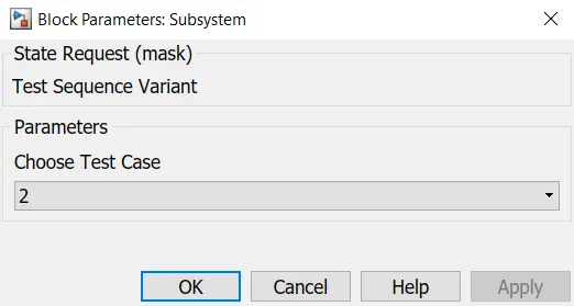
This test case has two Phases for the battery pack, i.e., Driving and after 10000 secs. Charging phase takes place.
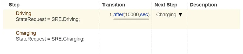
RESULT GRAPH:-
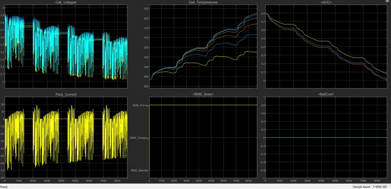
- from above graph the simulation is stopped at 8692 sec.
- because the SOC OF the battery cells is reached to 0%, so there is no power available in the battery.
- as charging time is just after 10000 sec so the simulation has stopped.
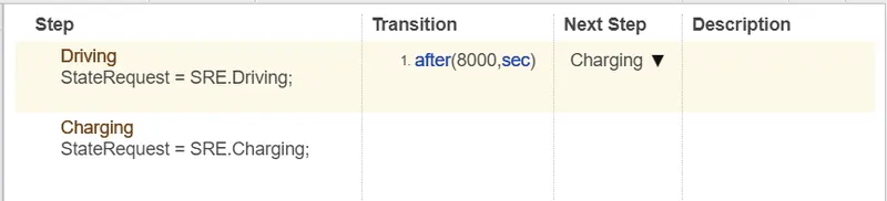
- FOR A CHANGE I HAVE CHANGED THE DRIVING TIME FROM 10000 TO 8000
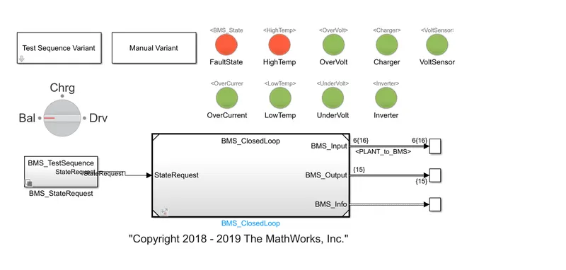
SO HERE TWO FAULTS ARE OCCURED
1. FAULT STATE
2. HIGH TEMP.
RSULT SCOPE:-
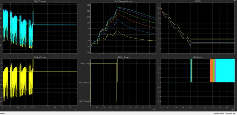
AFTER CHANGING THE DRIVING TIME SIMULATION IS RESUMED AND CHARGING IS STARTED BEFORE THE COMPLETELY DISCHARGING THE BATTERY.
TEST 3:-
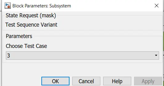
SELECTING TEST CASE:-
MODEL DASHBOARD:-
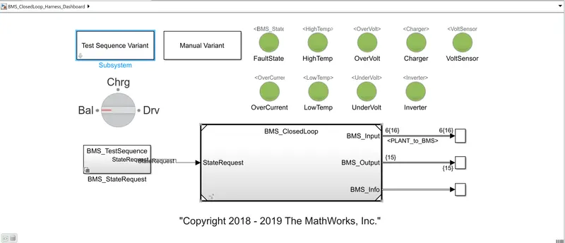
IN THIS TEST CASE :- NO ERROR OR FAULTS AS ALL SIGNLAS ARE GREEN
There is only a single phase here for the third test case, i.e. the charging phase.

RESULT:-
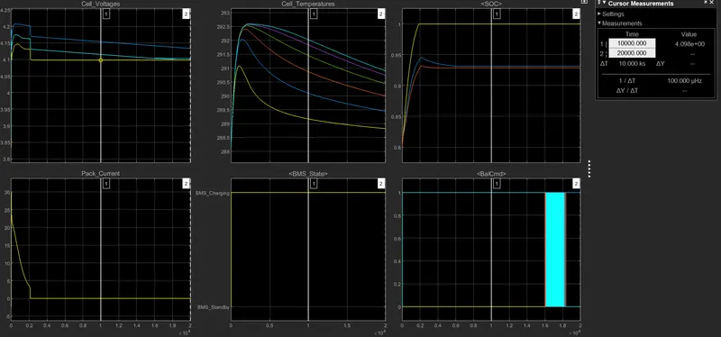
- as only charging mode is on: SOC is changed from 80% to 100 % and remains on standby mode.
- cell temperatue increased by 292.5 K till 100 % soc after 100% soc temp of cells is reduced to ambient temperature
- charging voltage is carried 4.2 voltage while charging.
2.What is coulomb counting? Refer to the above model and explain how BMS implements coulomb counting for SOC estimation ?
Hint :(Download the file from the link and go to SOC estimation model-ECU block)
THERE ARE THREE TYPES OF ESTIMATING SOC
1. COULOMB COUNTING.
2. EXTENDED KALMAN FILTER.
3. UNSCENTED KALMAN FILTER.
ANS:-
Coulomb counting:-
Coulomb counting is a technique used to track the state of charge of a battery pack.
It works by integrating the active flowing current (measured in amps) over time to derive the total sum of energy entering or leaving the battery pack.
This produces a capacity that is typically measured in Amp-hours.
The Coulomb counting method measures the discharging current of a battery and integrates the discharging current over time in order to estimate SOC.
It is done to estimate the SOC(t), which is estimated from the discharging current, l(t), and previously estimated SOC values, SOC(t-1).
SOC is calculated by the following equation:
soc(t) = soc(t - 1) +I(t)/Q(N)xdt
Where,
SOC(t) = State of charge at estimated time;
I(t) = Discharging current;
Q(N) = Nominal battery capacity.
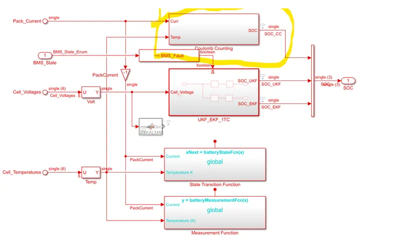
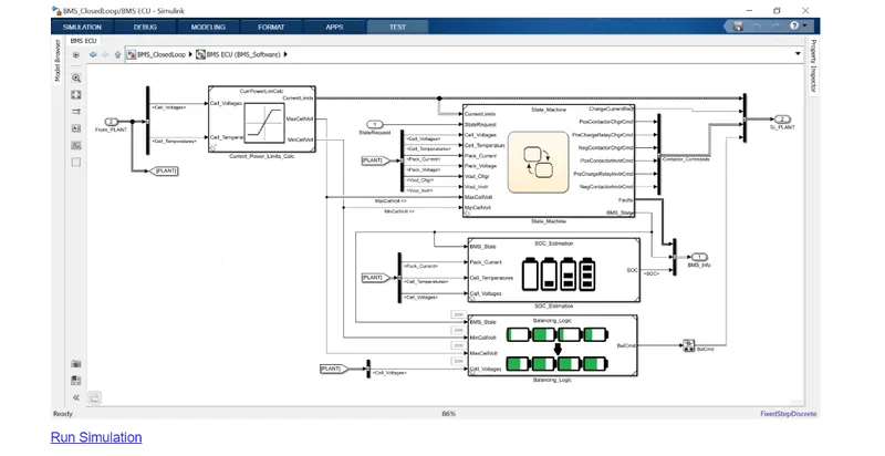
IMPLEMANTATION OF COULOMB COUNTING IN BMS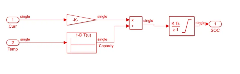
• The discharge current signal is converted from the physical system using a gain block.
• The gain block is integrated by 1/30X3600 is applied to the integrated signal which gives us the discrete data.
• The temperature data is divide by using a lookup table with the discharge current rate.
• The output is then integrated with a discrete-time integrator block with a sample time of 0.1 sec to calculate the SOC of the battery
pack.